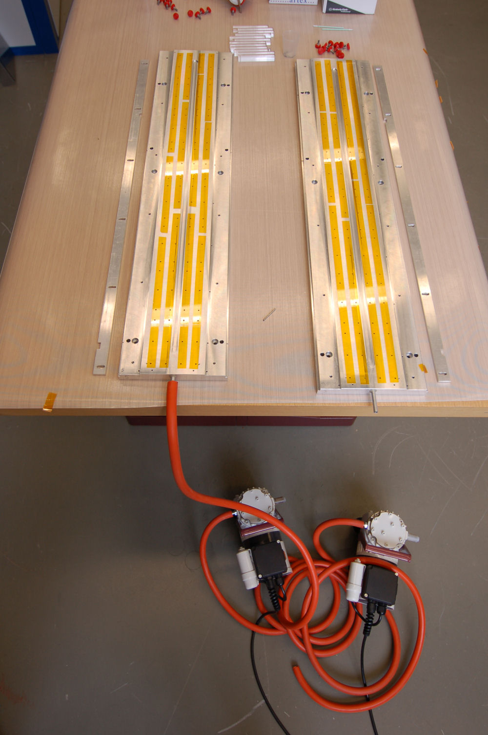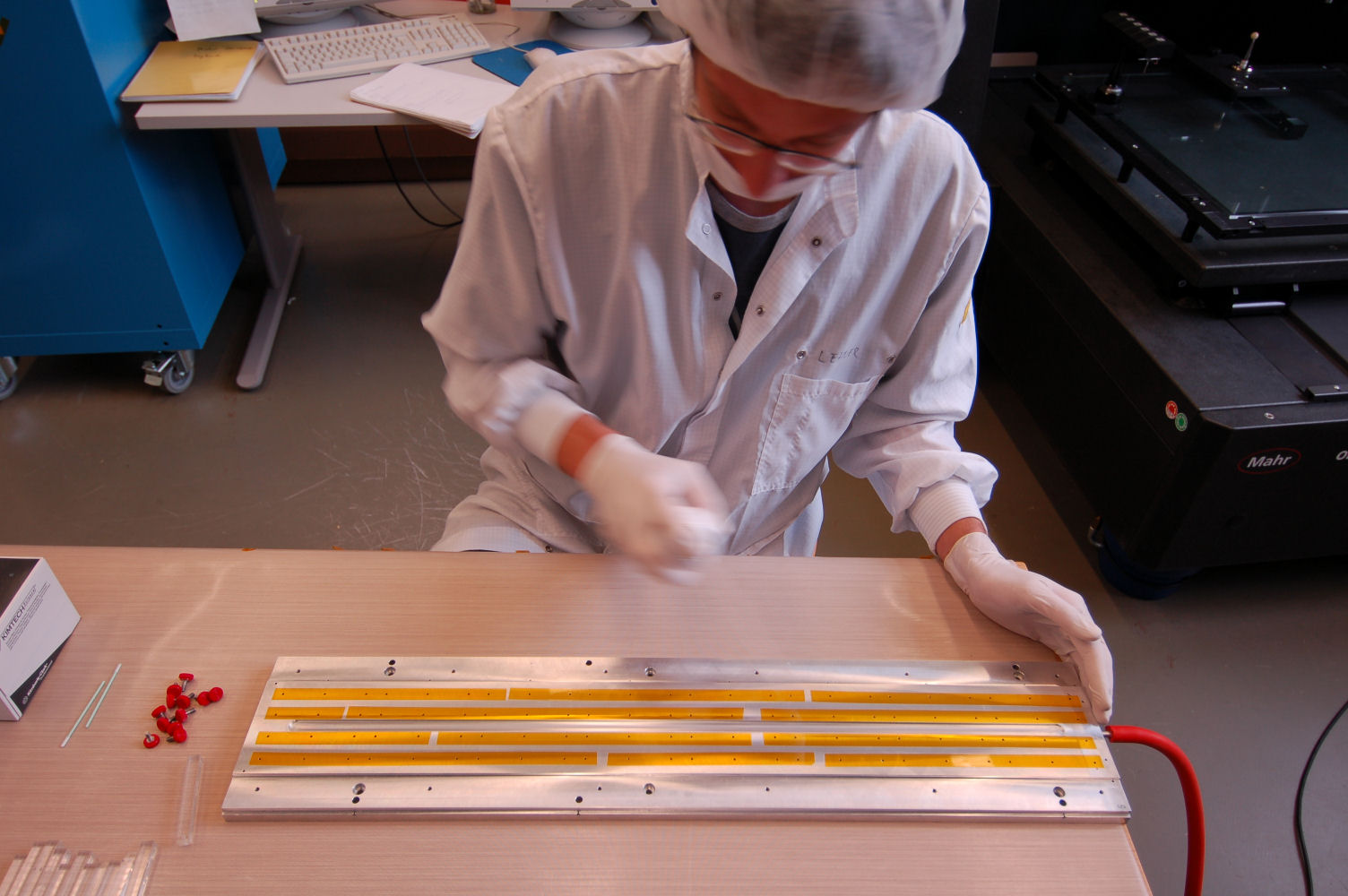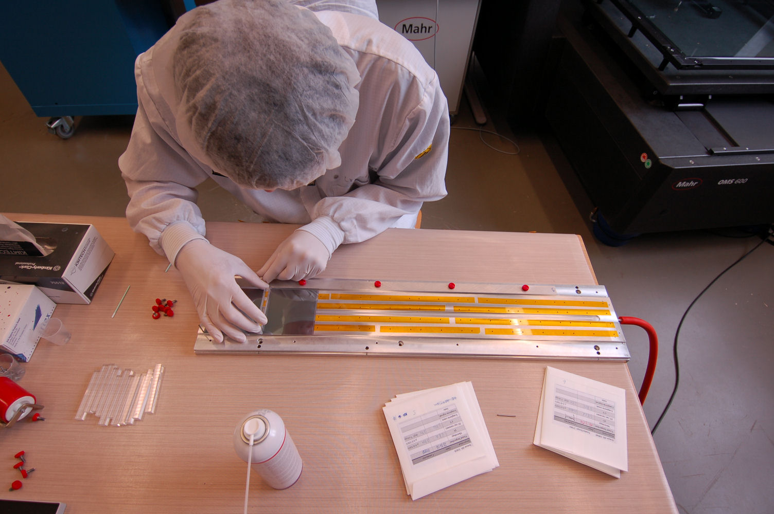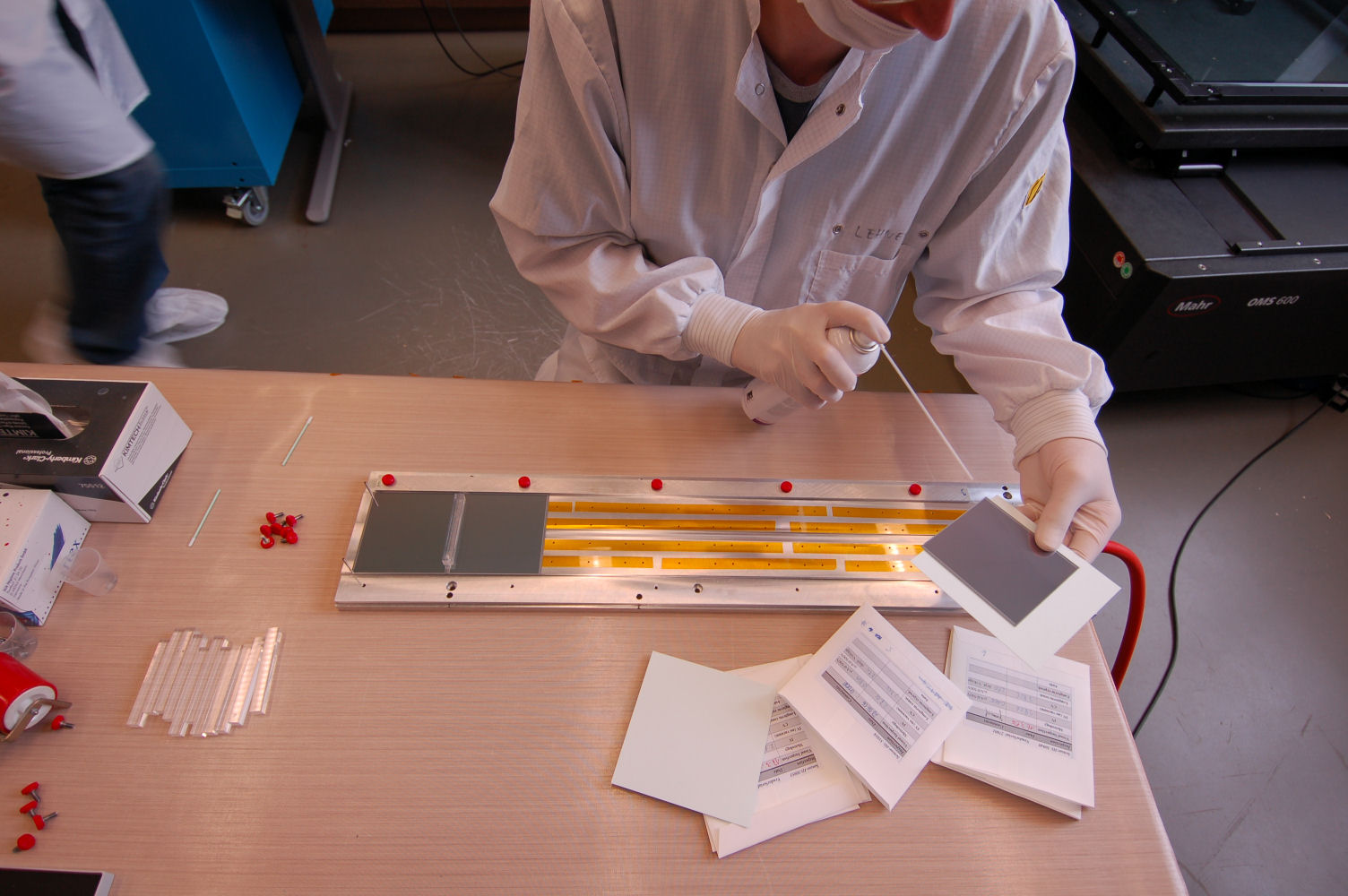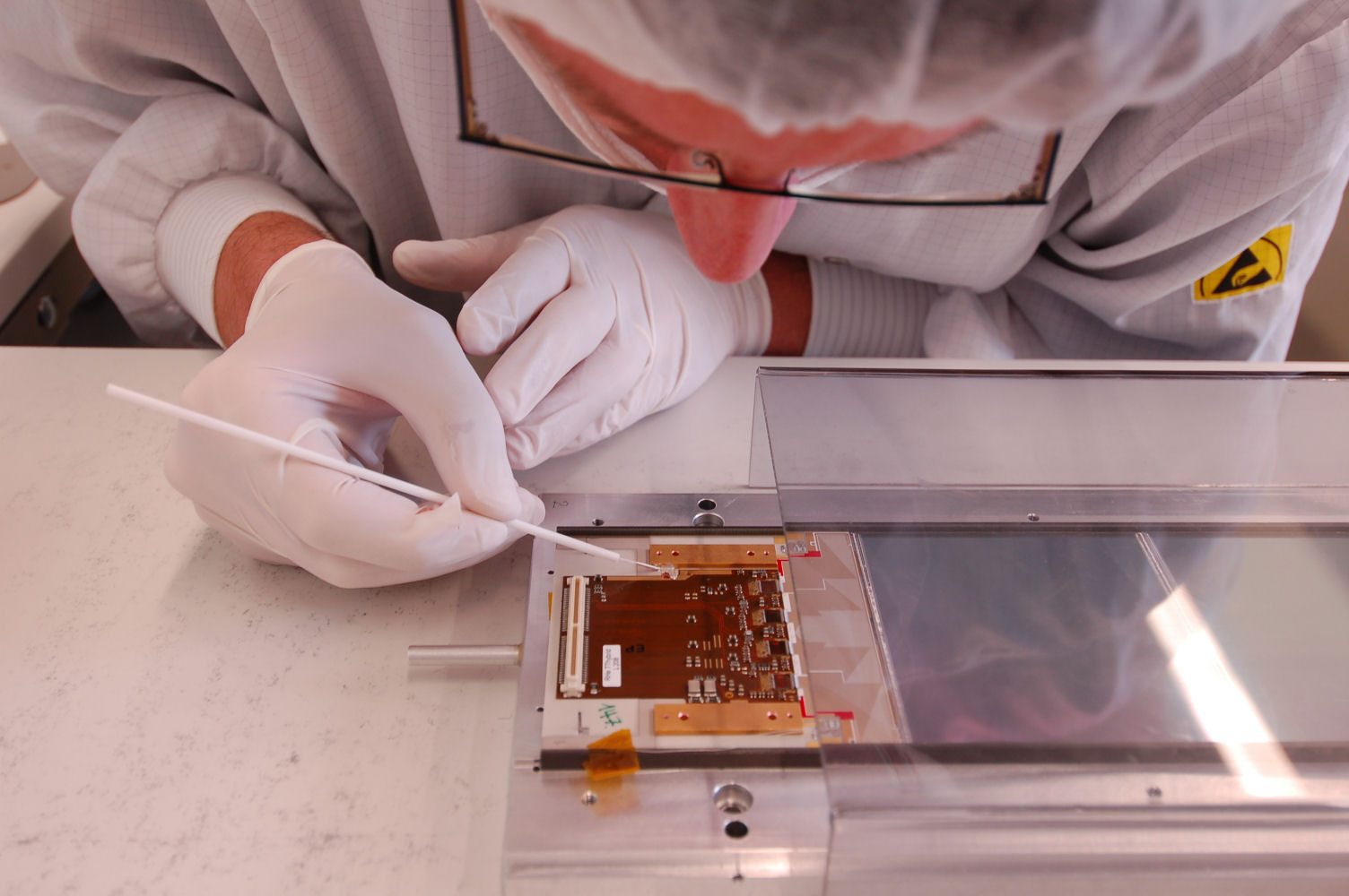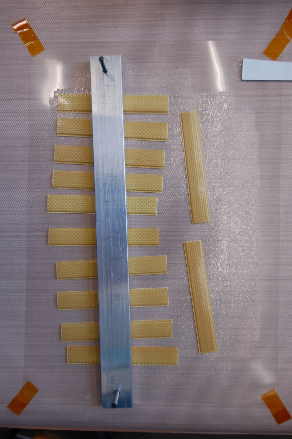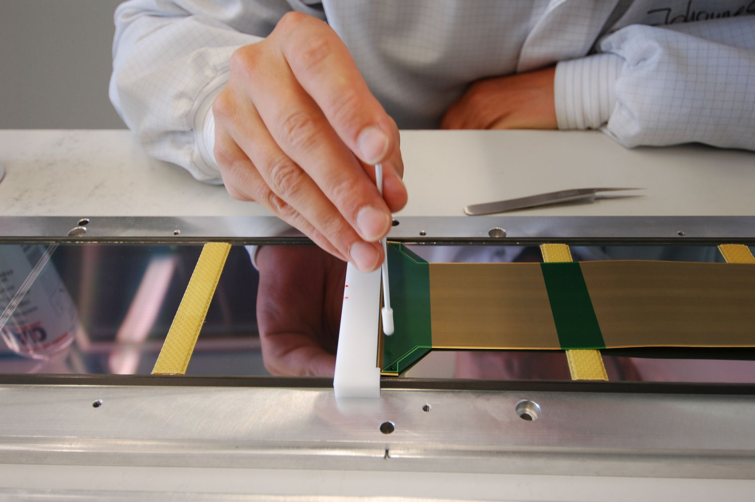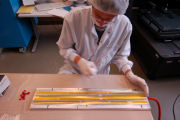
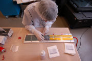
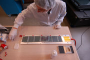
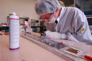
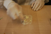
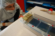
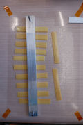
Cleaning the template
|

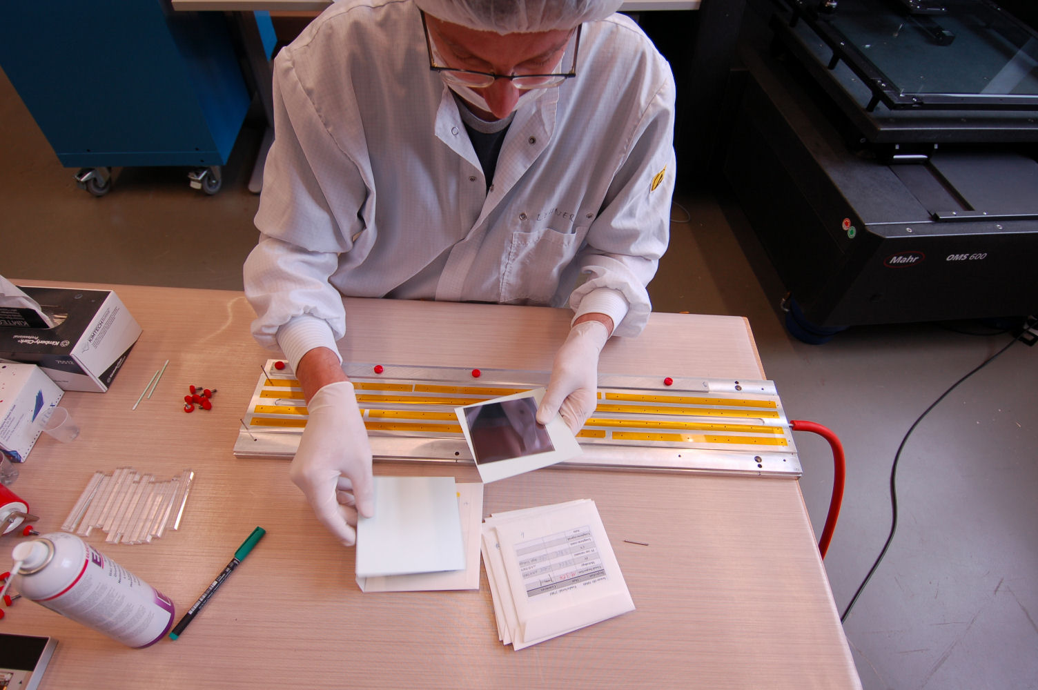
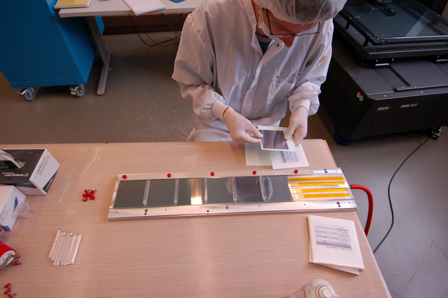
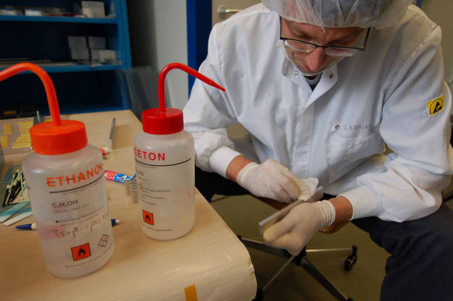
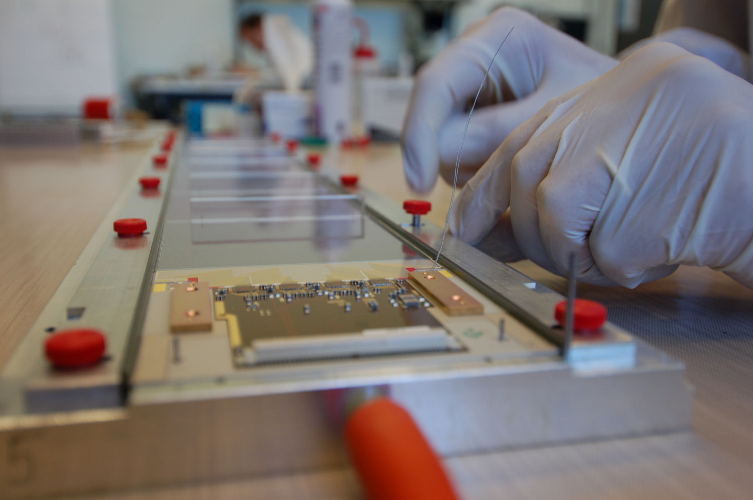
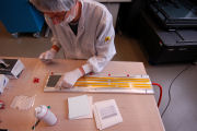
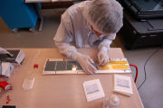
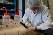
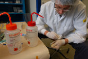
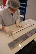
Selecting the 1st sensor
|
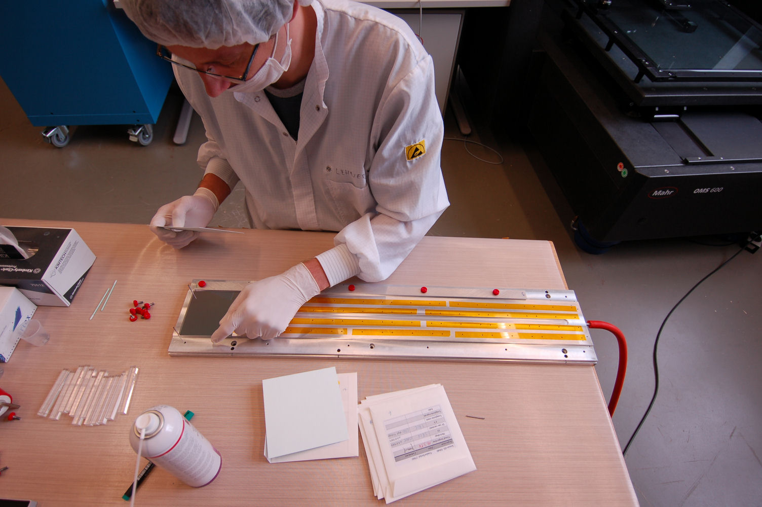
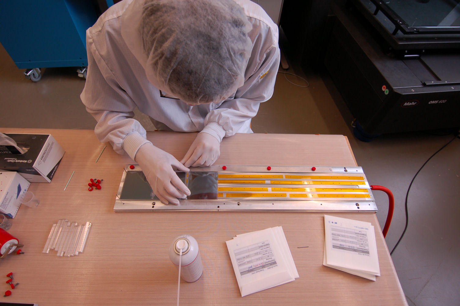
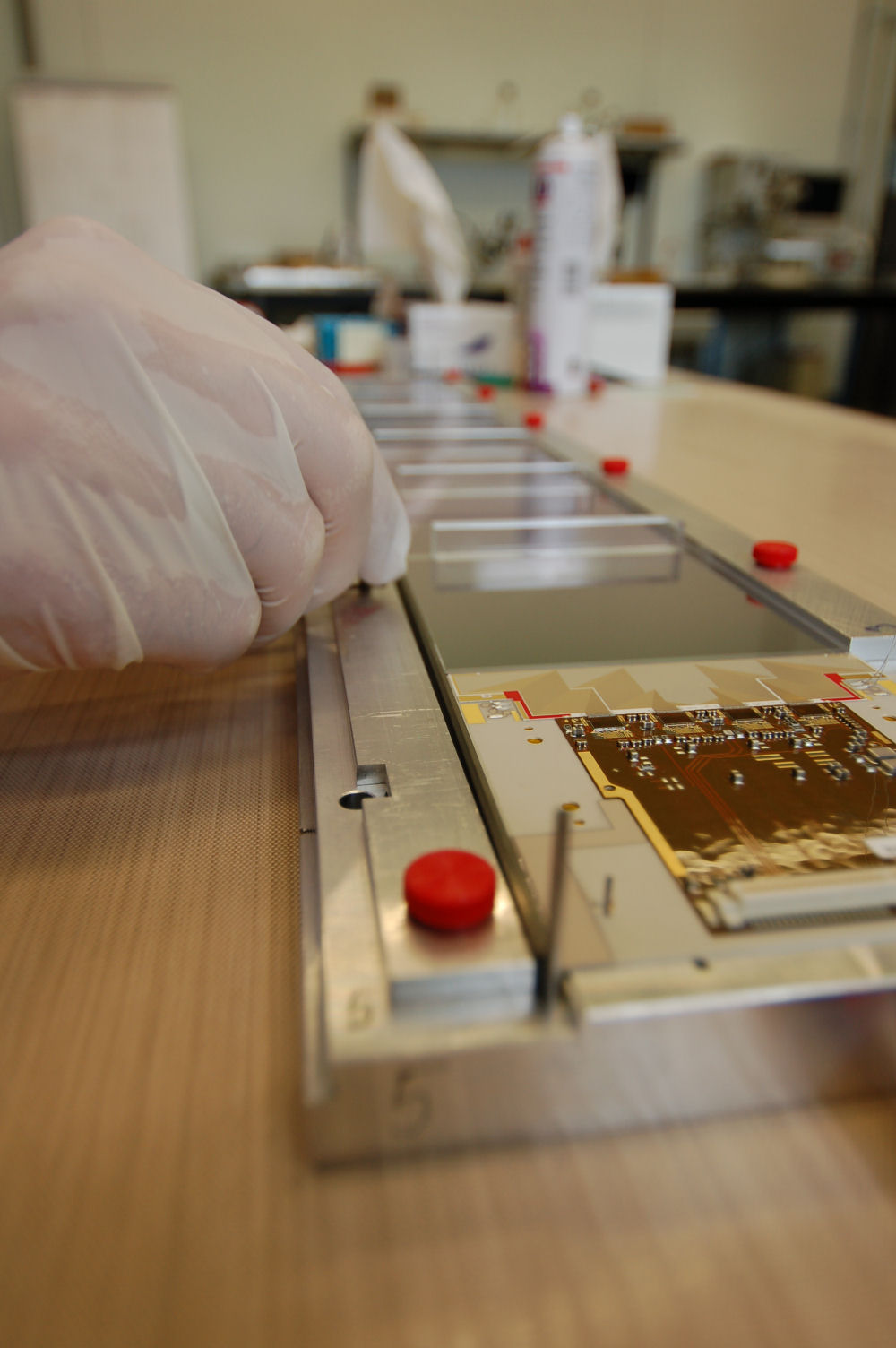
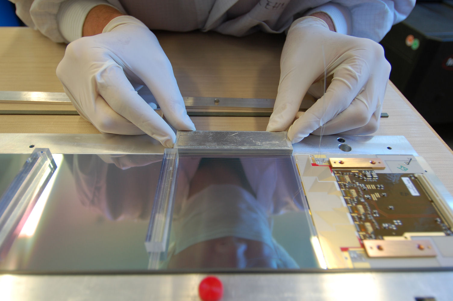
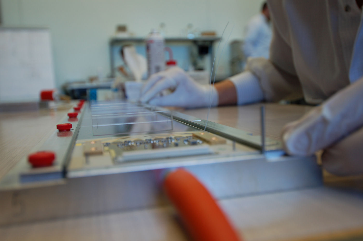
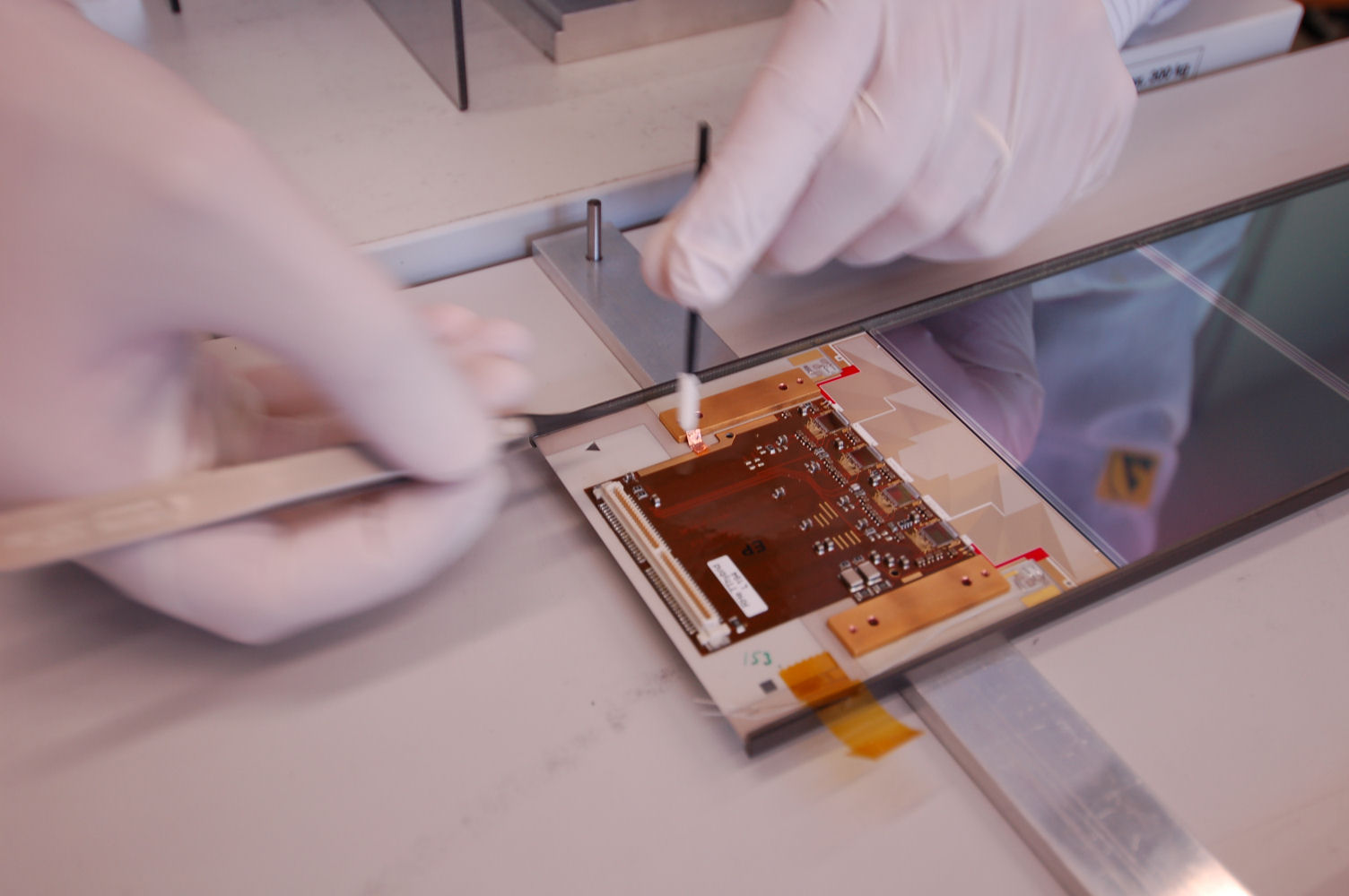
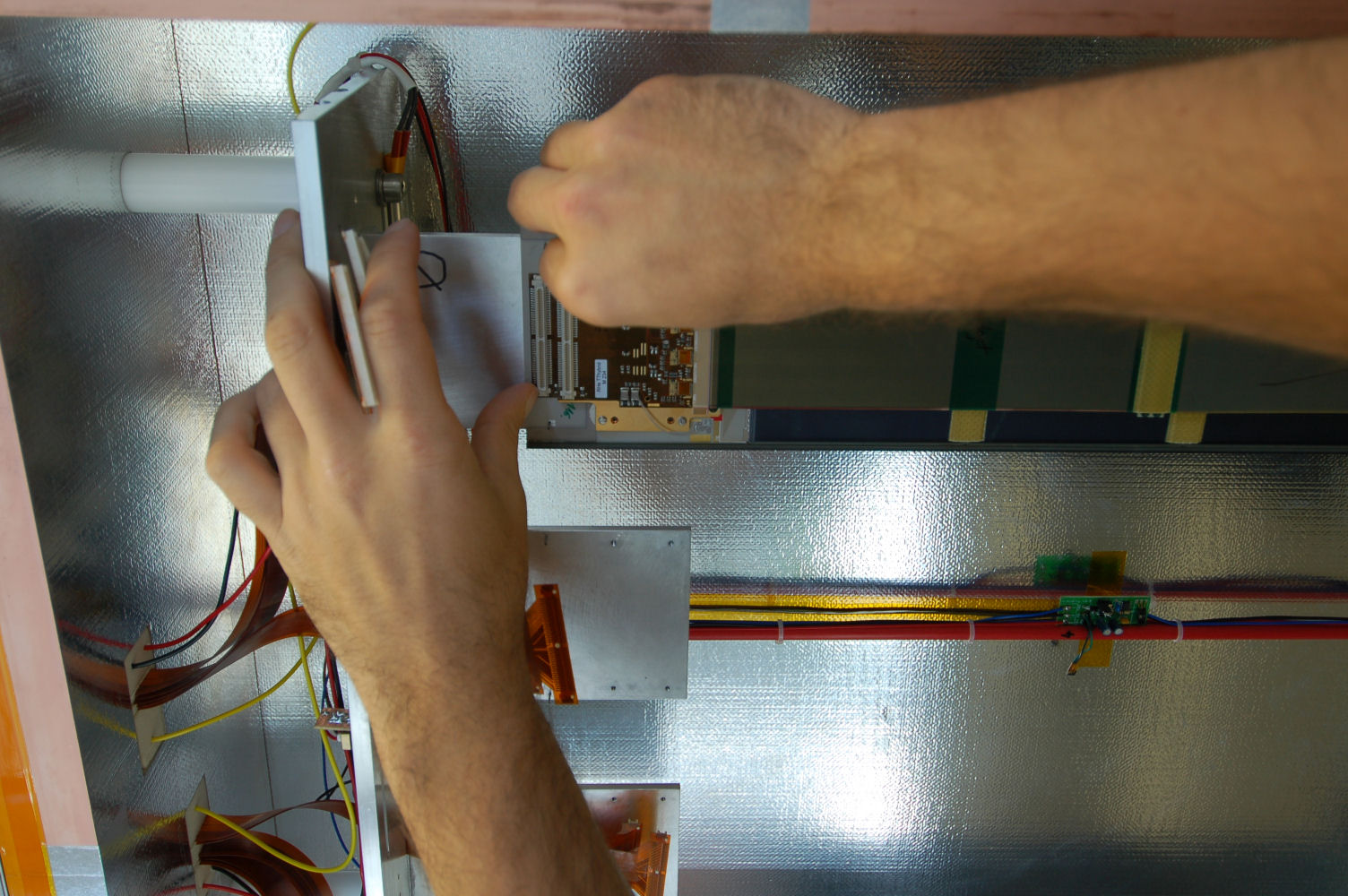
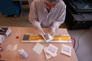
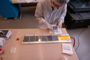
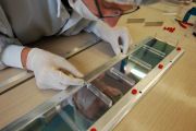
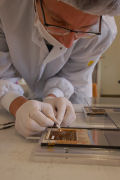
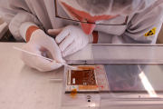
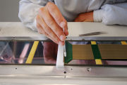
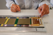
Placing the 1st sensor
|
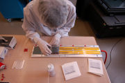
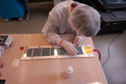
Selecting the 2nd sensor
|

Placing the 2nd sensor
|

Selecting the 3rd sensor
|
Placing the 3rd sensor
|
Placing the 4th sensor
|
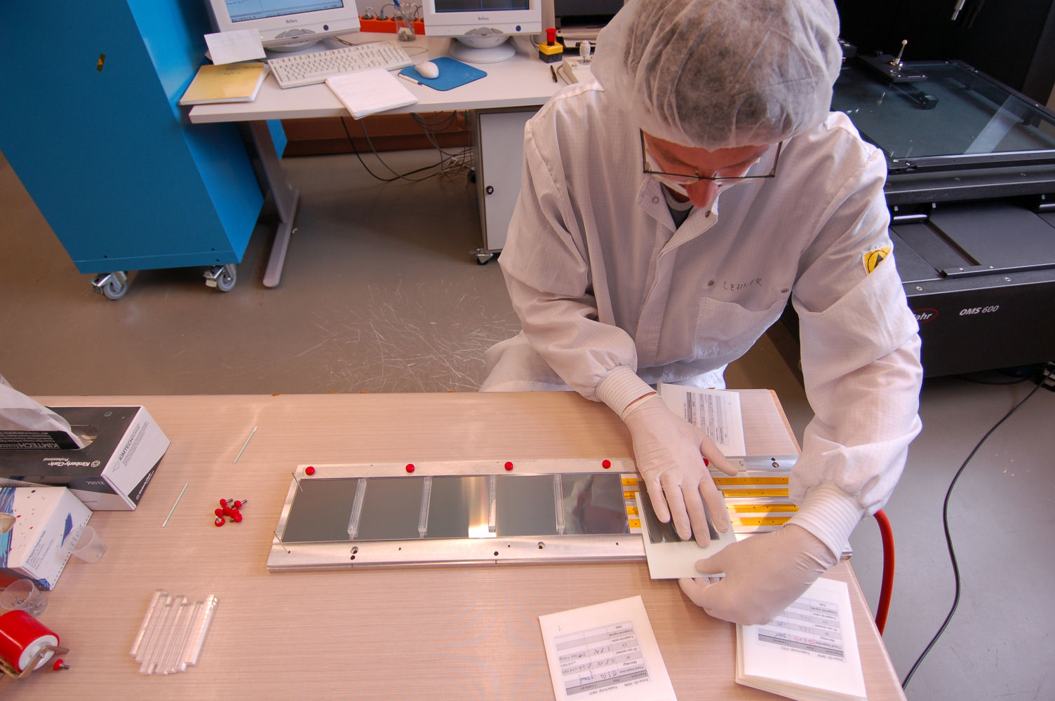
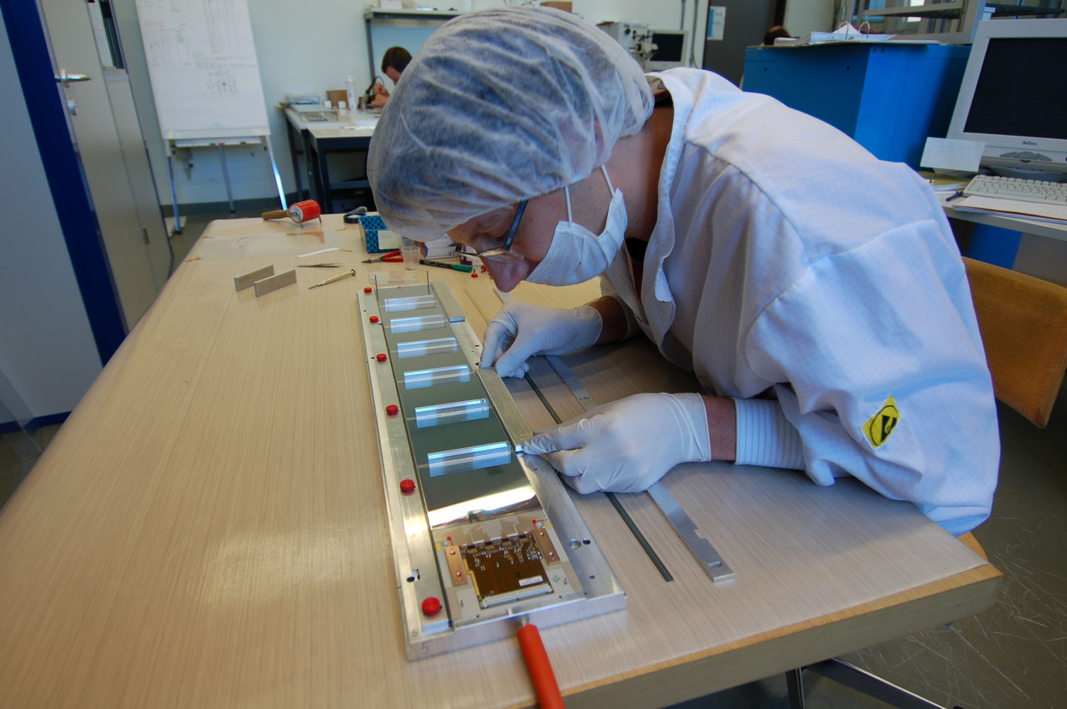
Placing the 5th sensor
|

Placing the 6th sensor
|
Selecting the 7th sensor
|
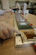
Placing the 7th sensor
|
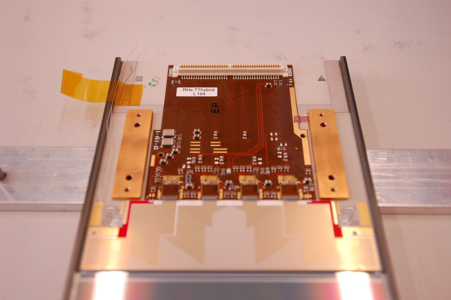
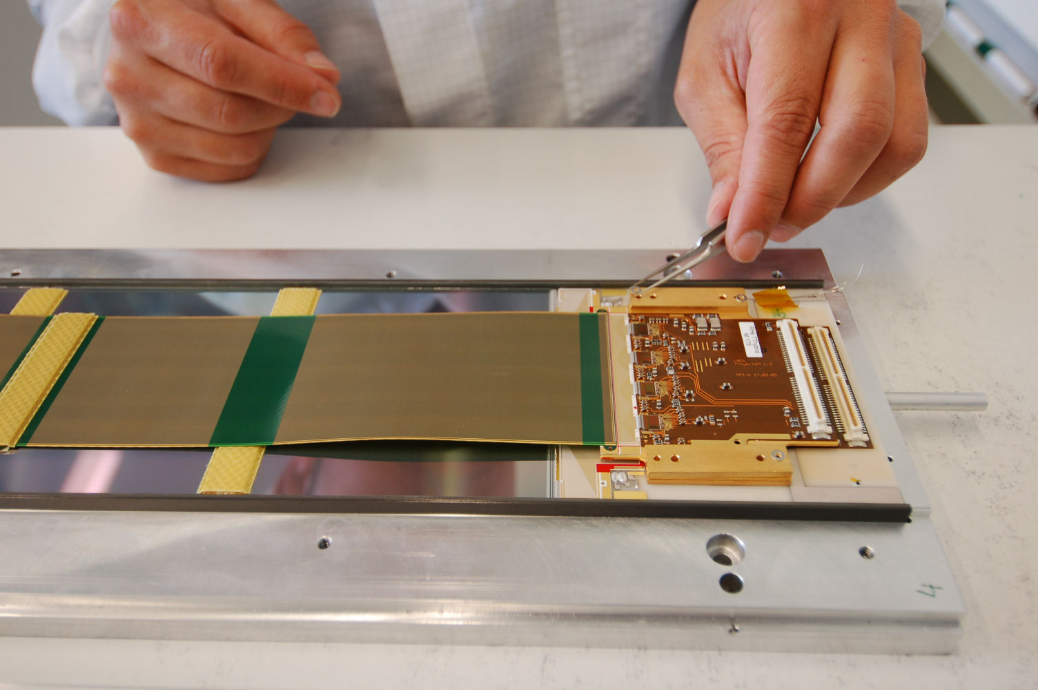
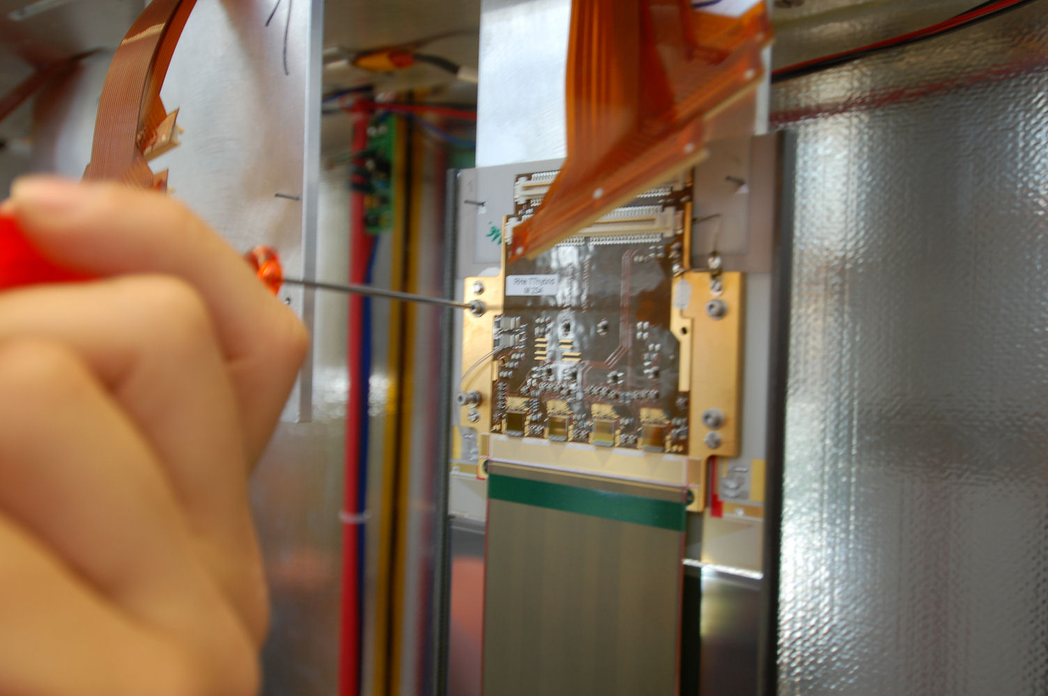
Selecting the hybrid
|
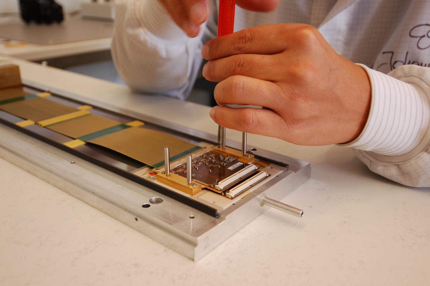
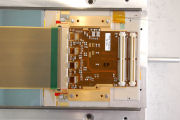
Placing the hybrid
|
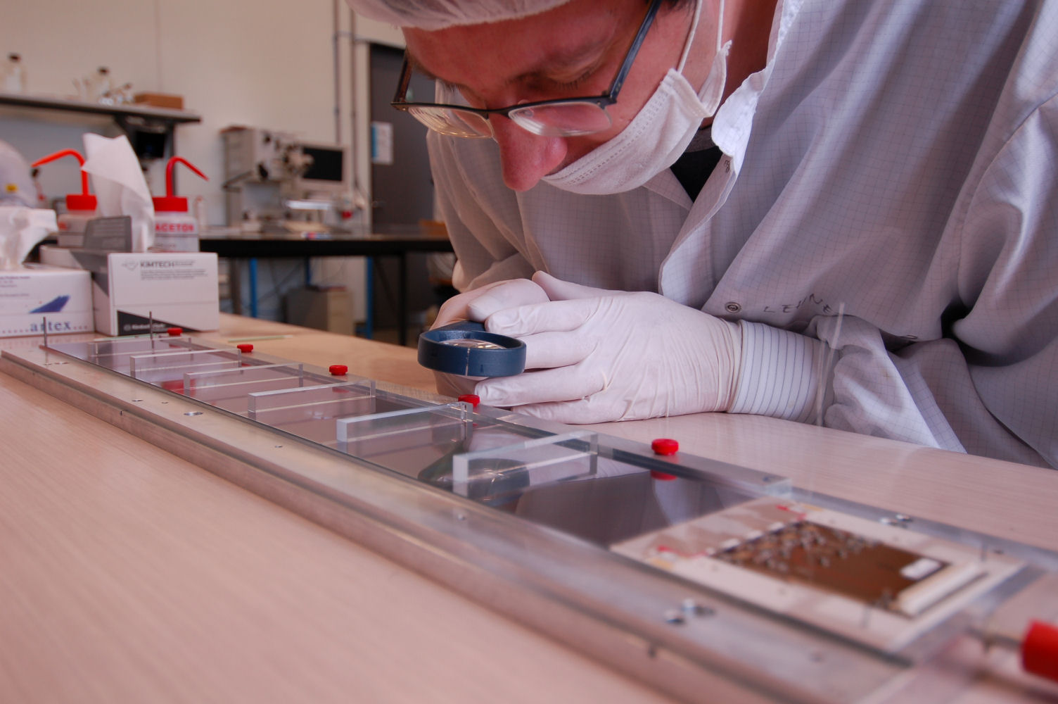
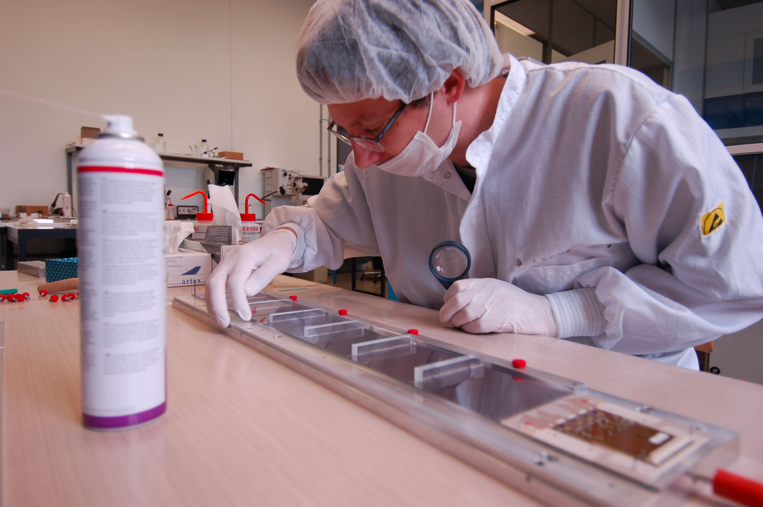
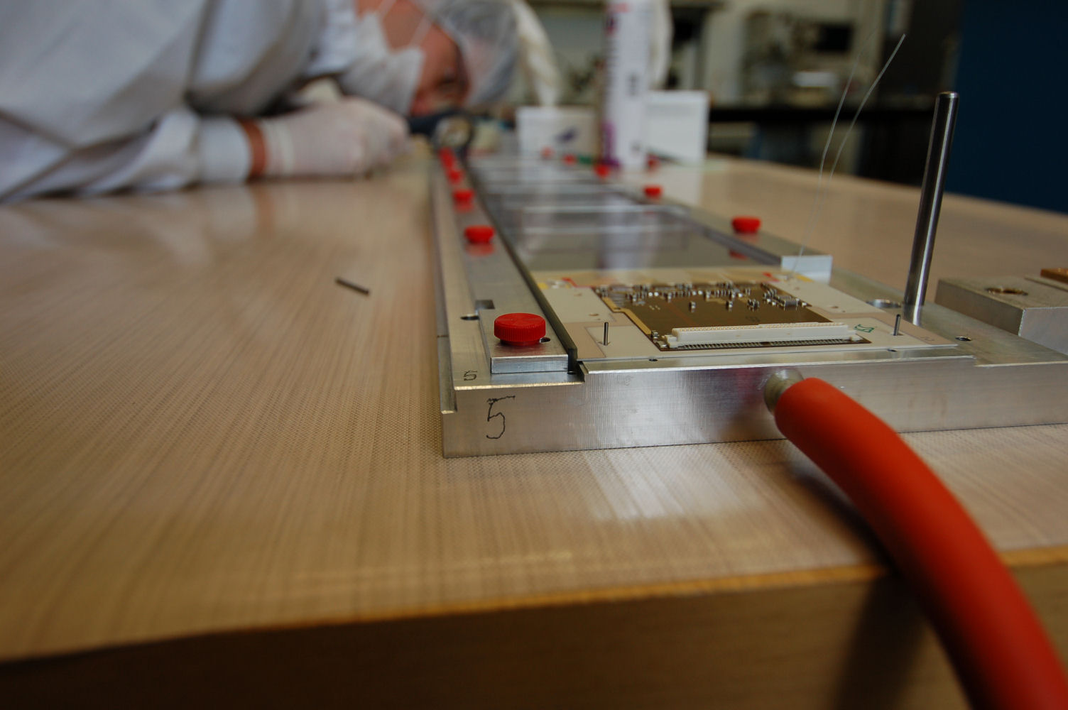
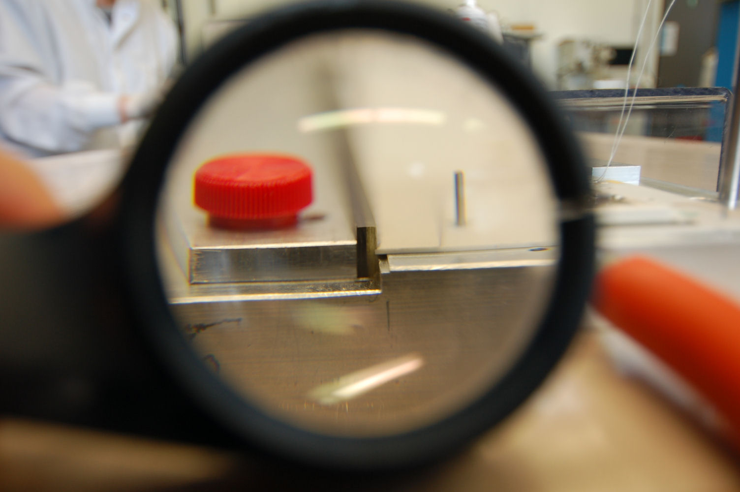
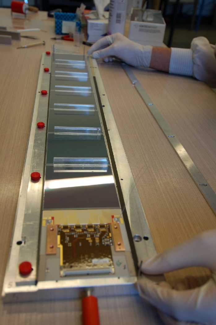
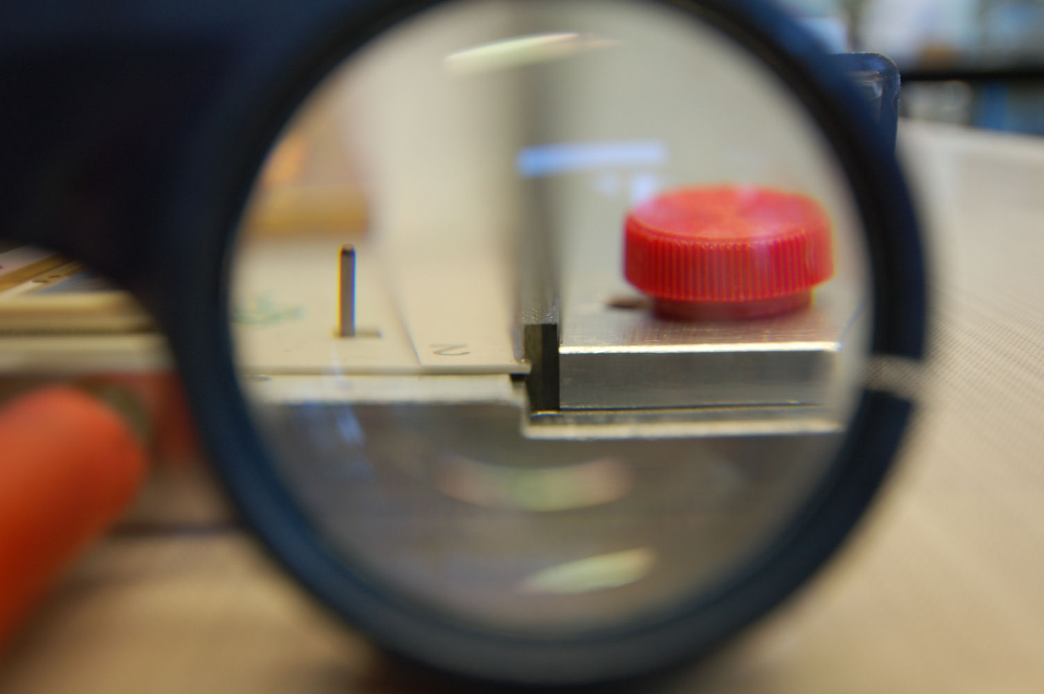
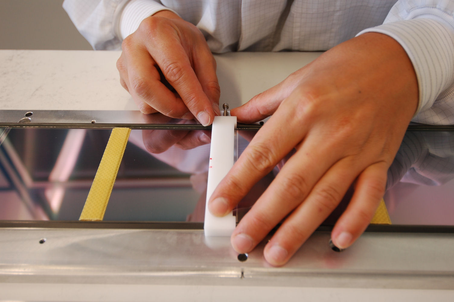
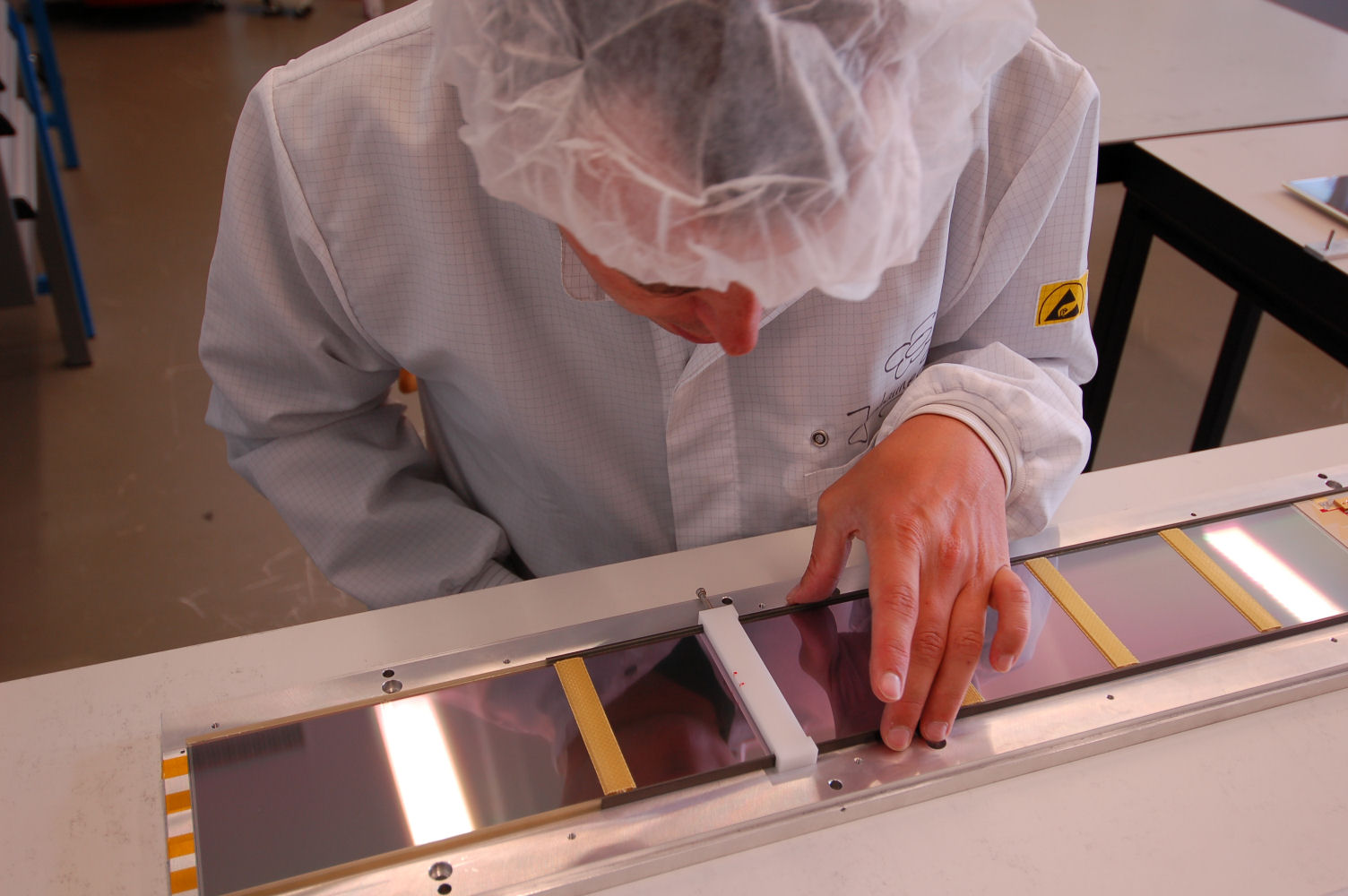
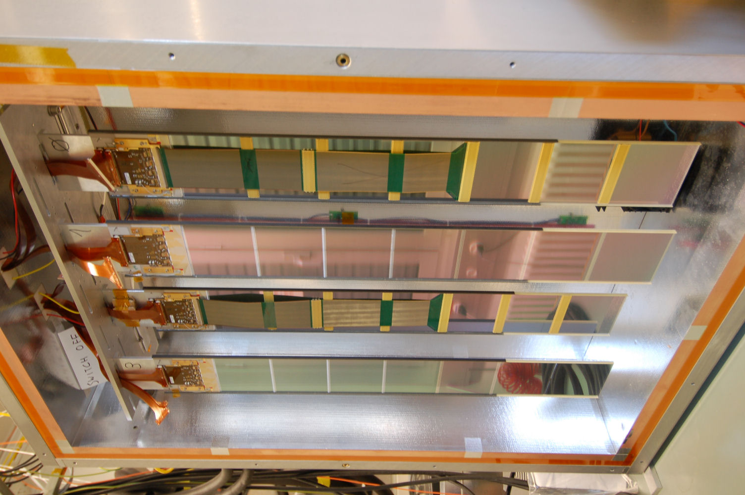
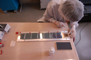
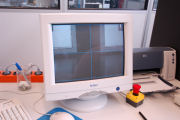
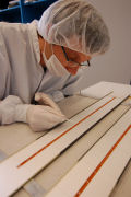
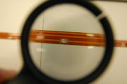
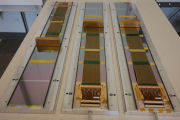
Checking the sensor alignment
|
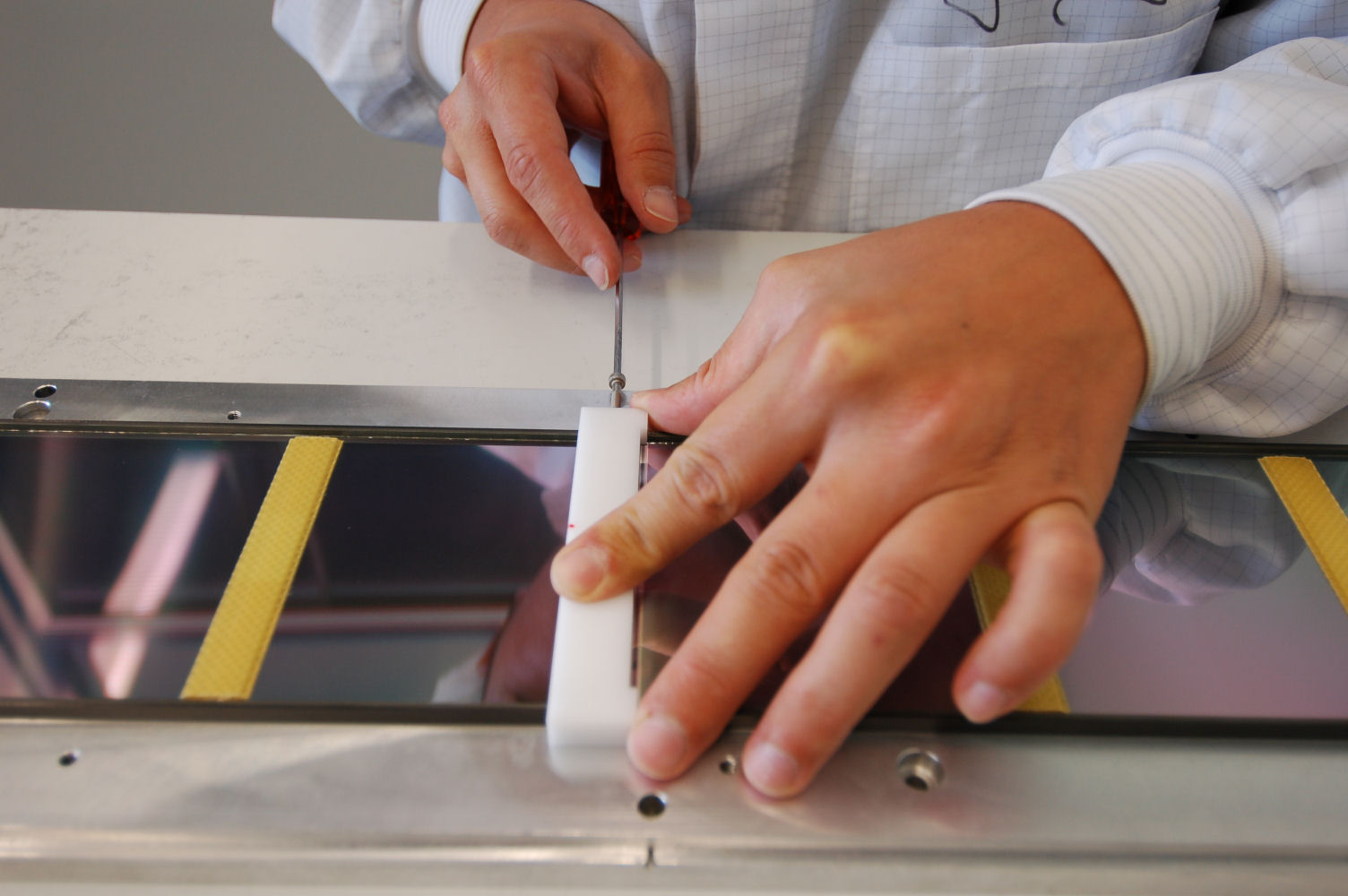
Correcting the sensor alignment
|
Checking again
|
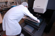
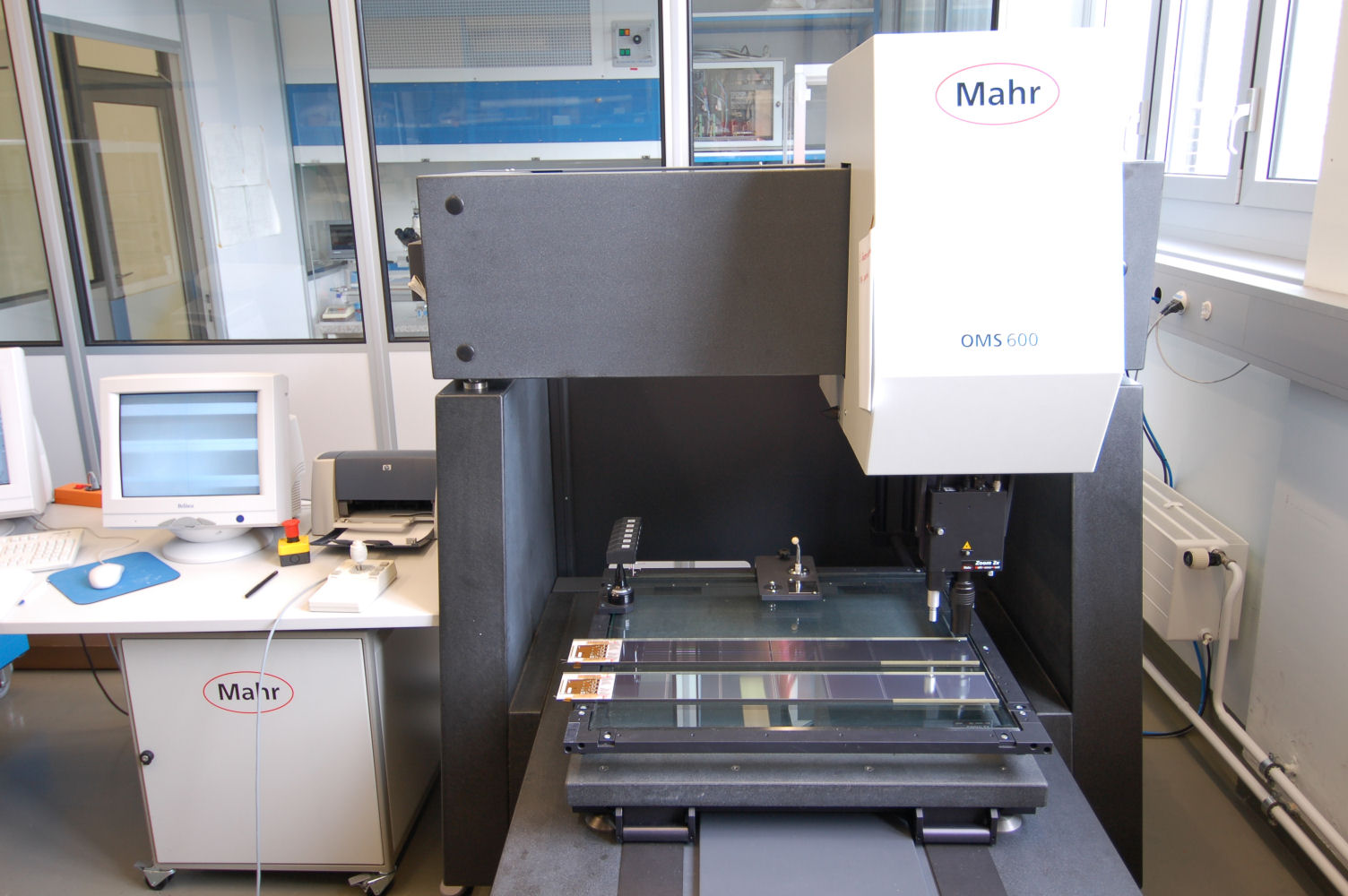
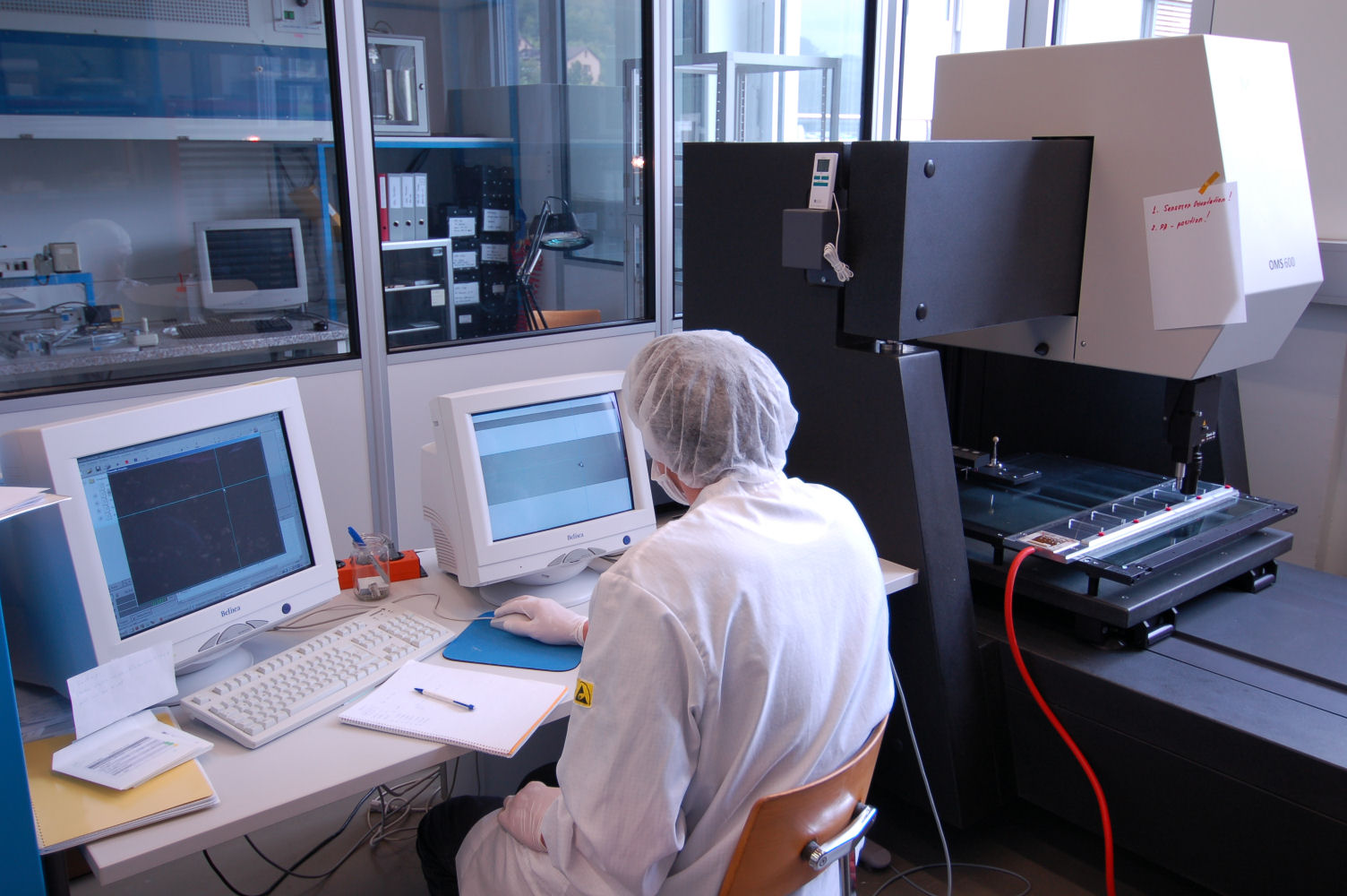
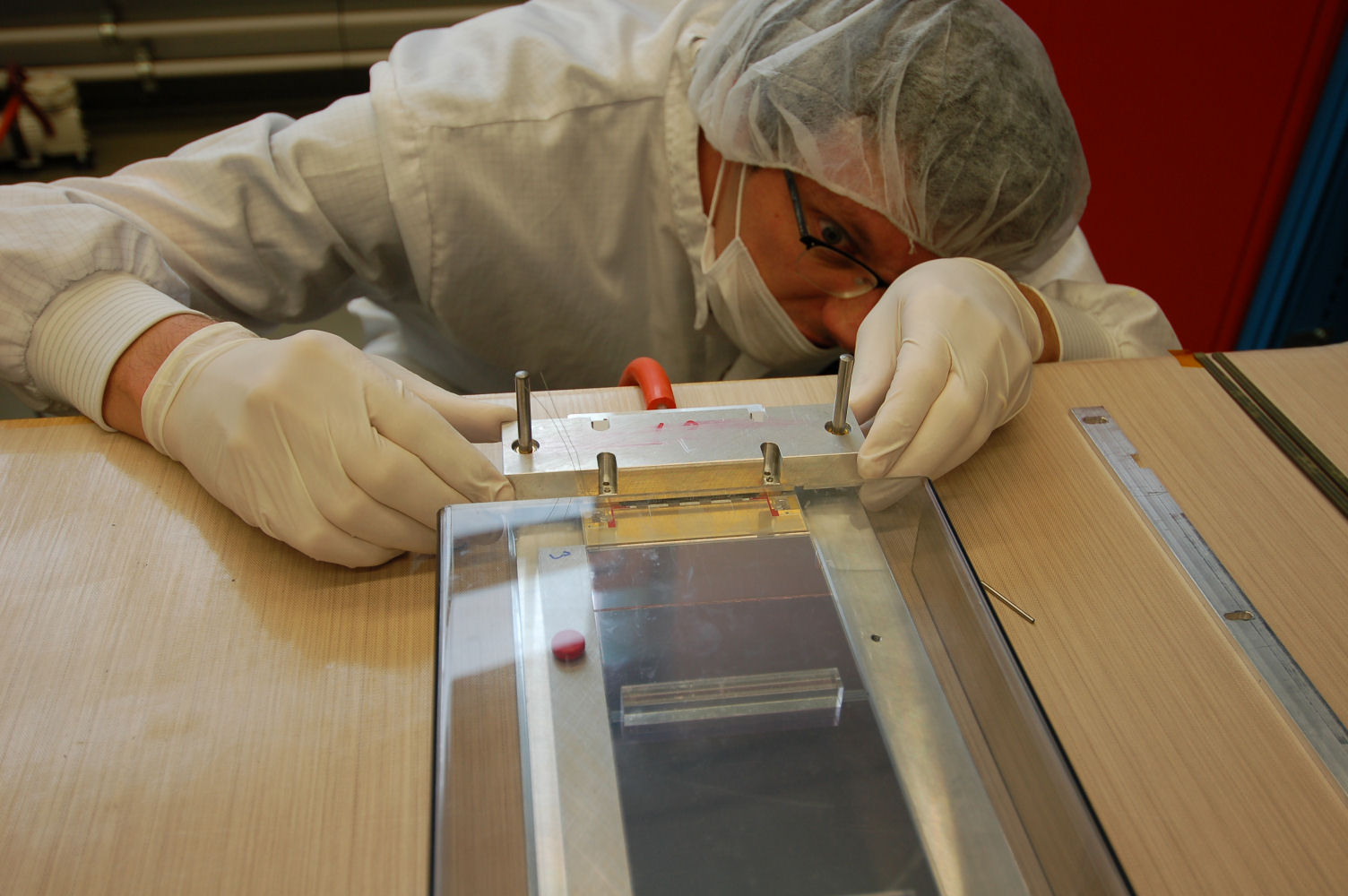
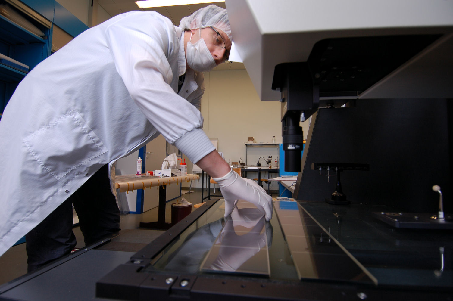
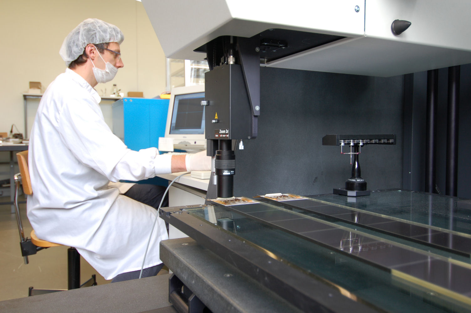
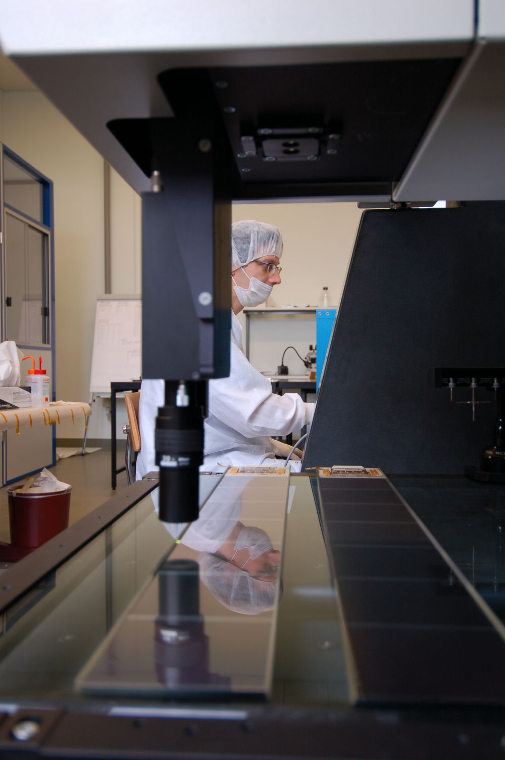
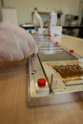
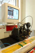
Placing the module under the CMM
|

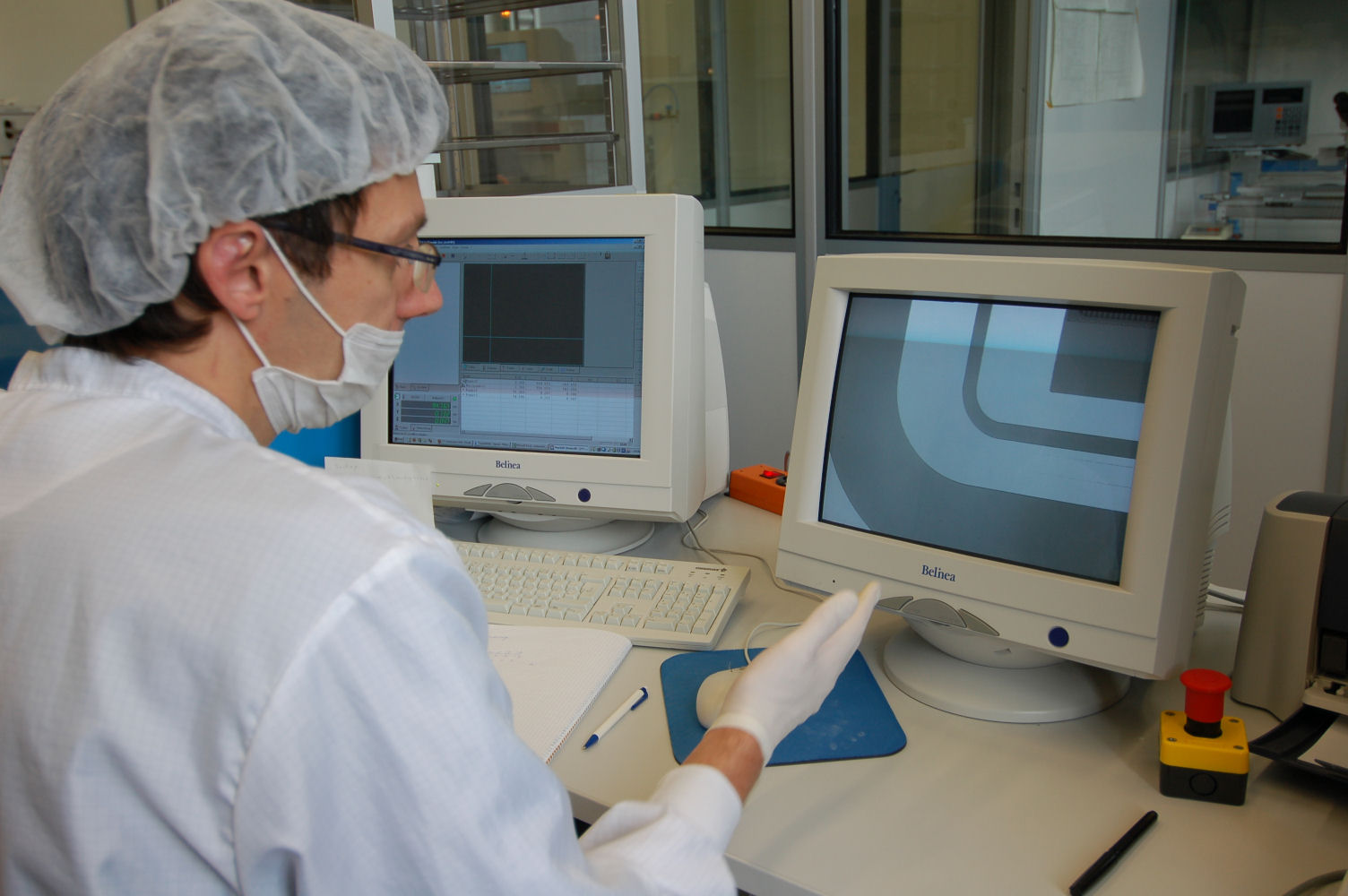
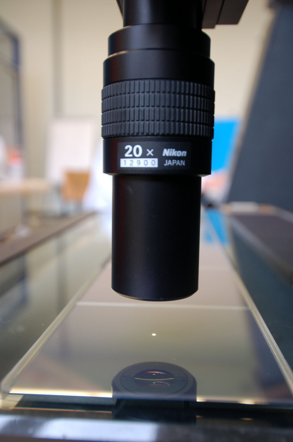
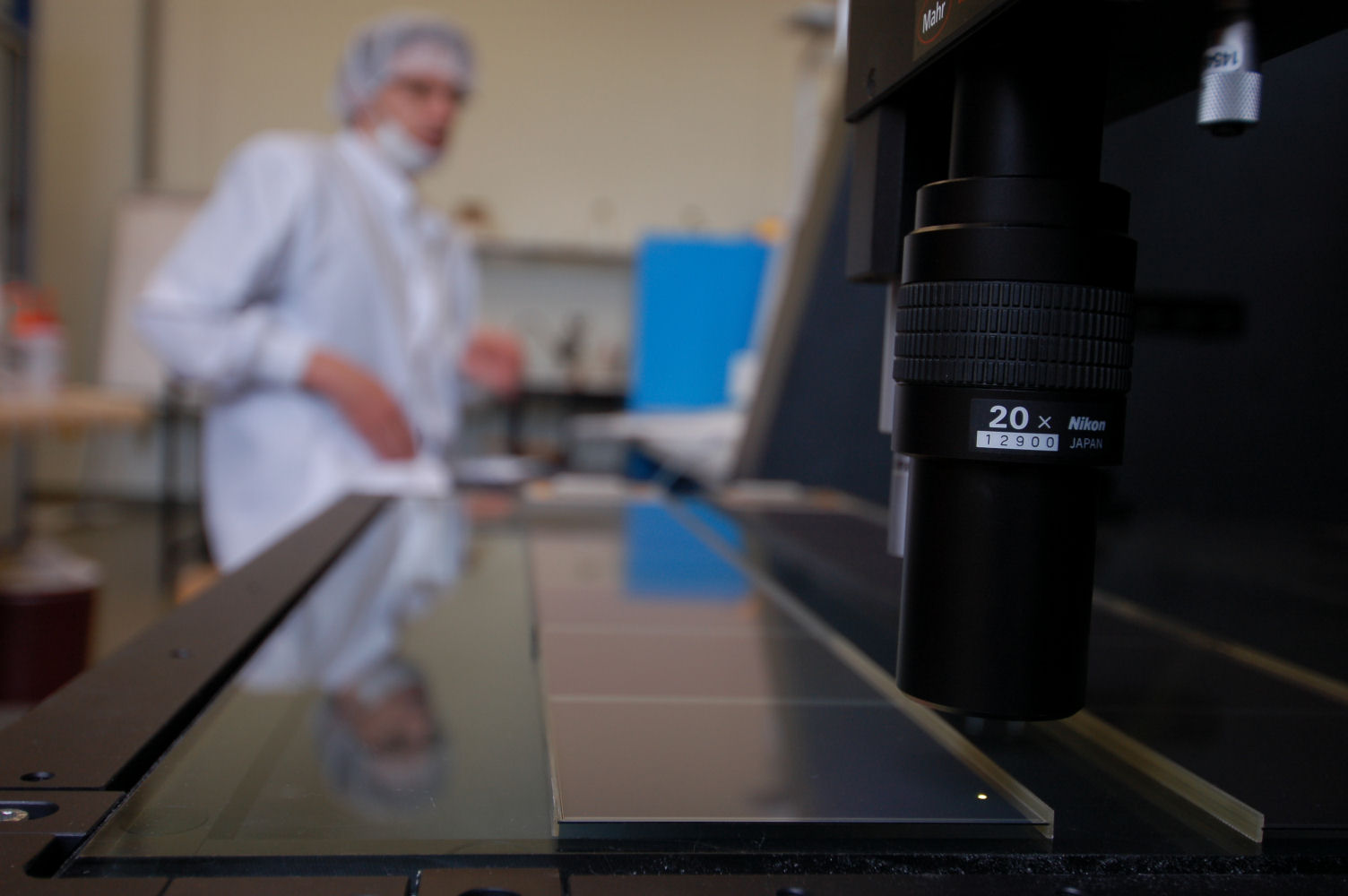
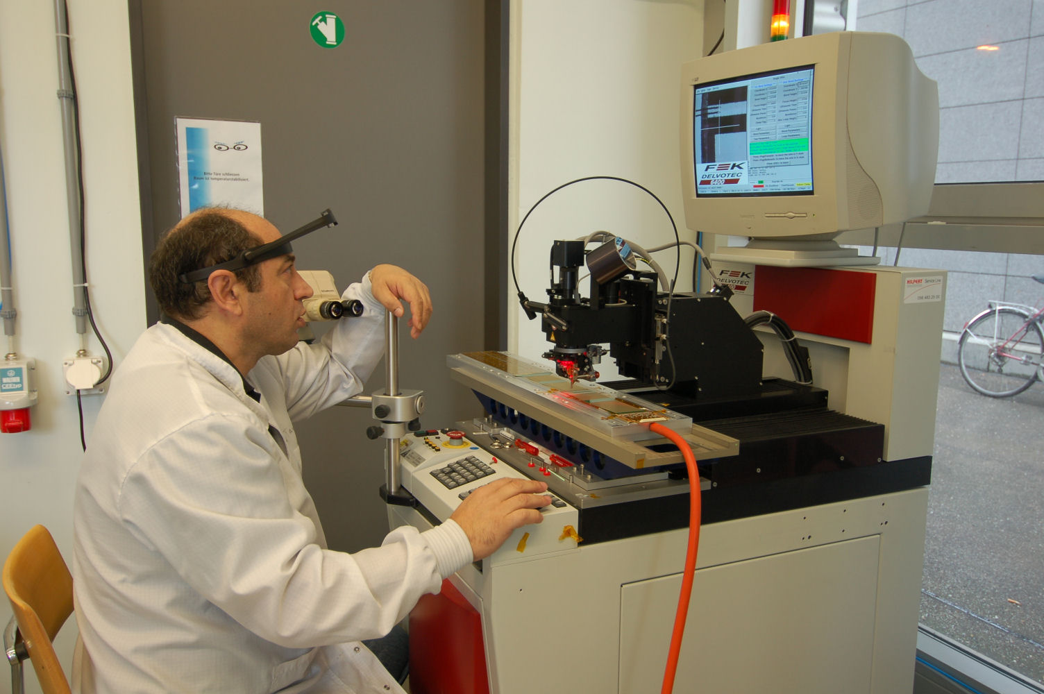
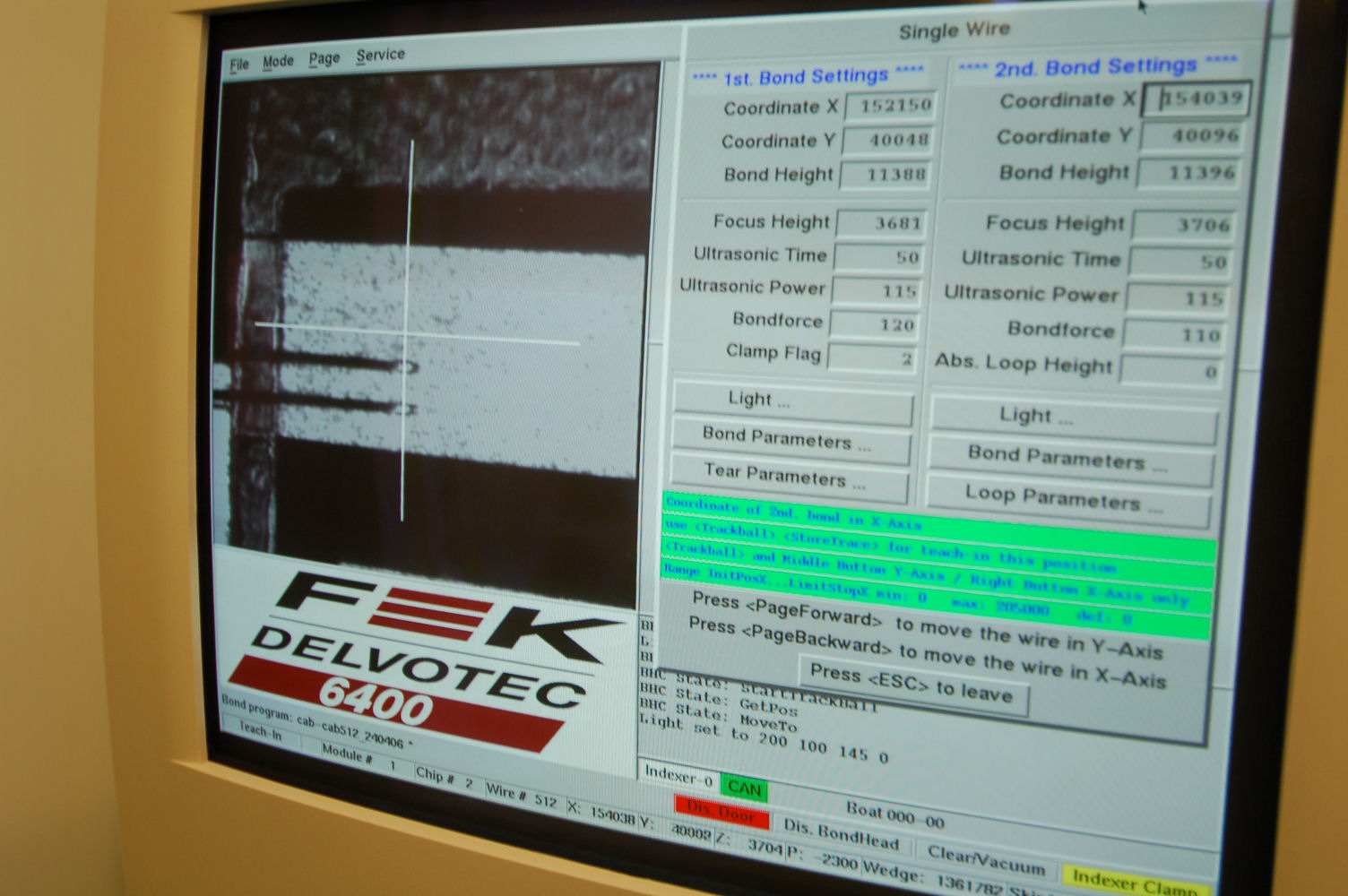
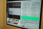
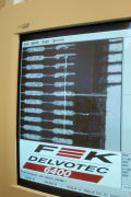
Measuring the sensor alignment
|
Measuring the sensor alignment
|
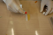
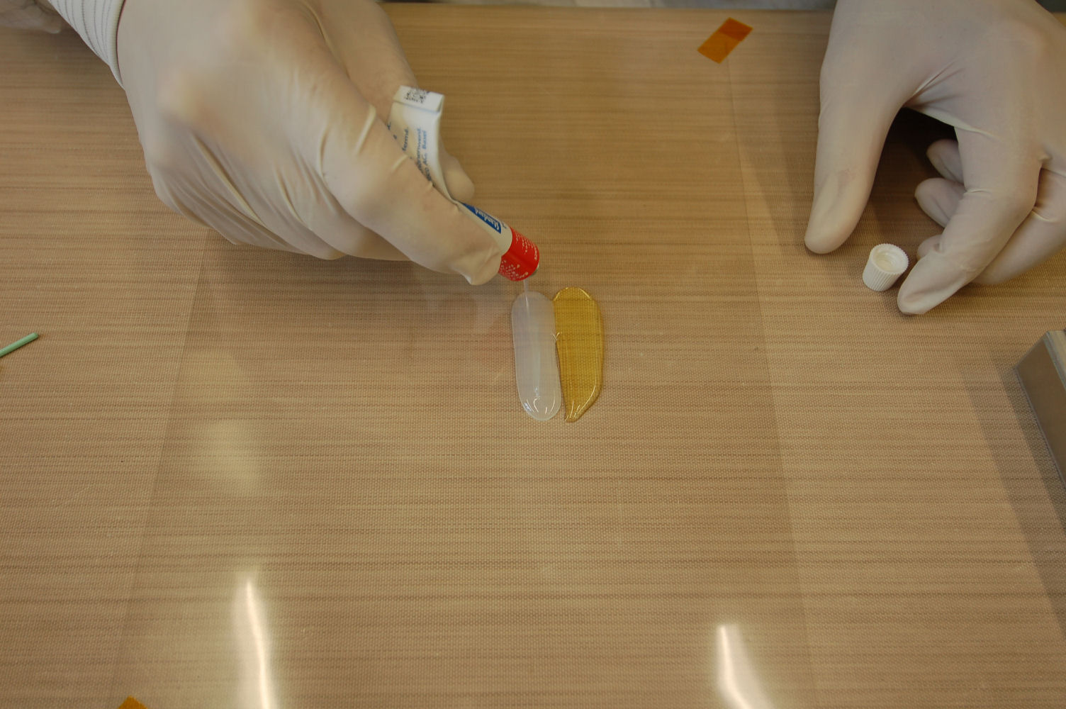
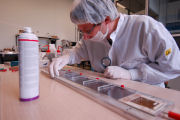
Preparing the glue
|
Mixing the glue
|

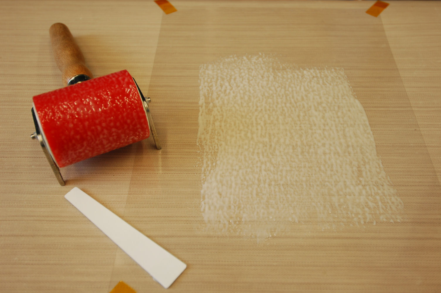
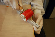
Transfering the glue to the roller
|
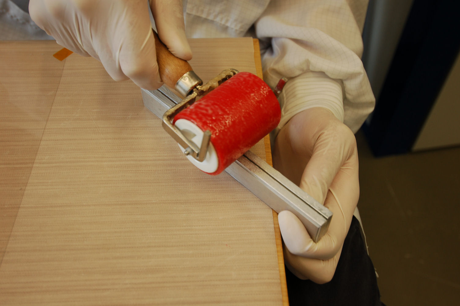
Transfering the glue to the stencils
|
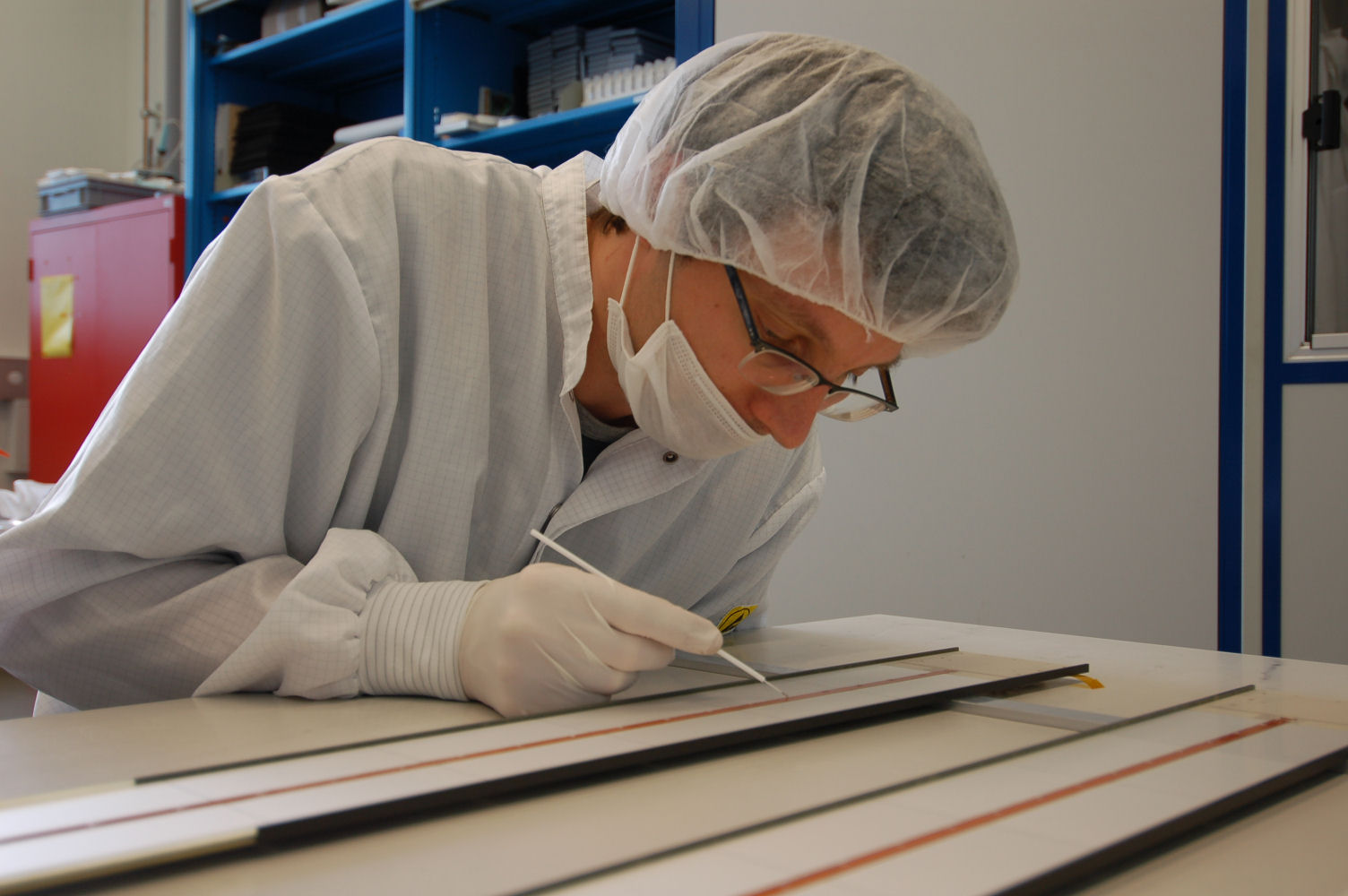
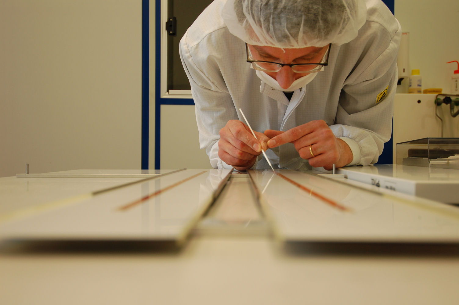
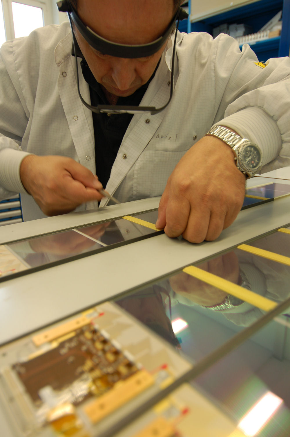
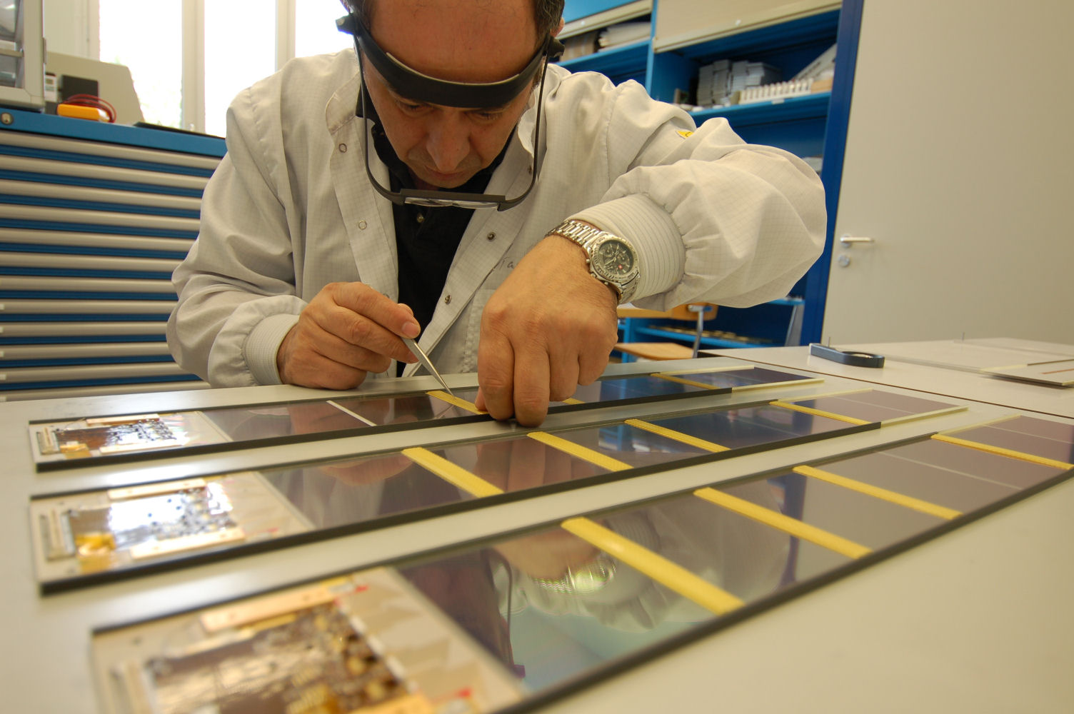
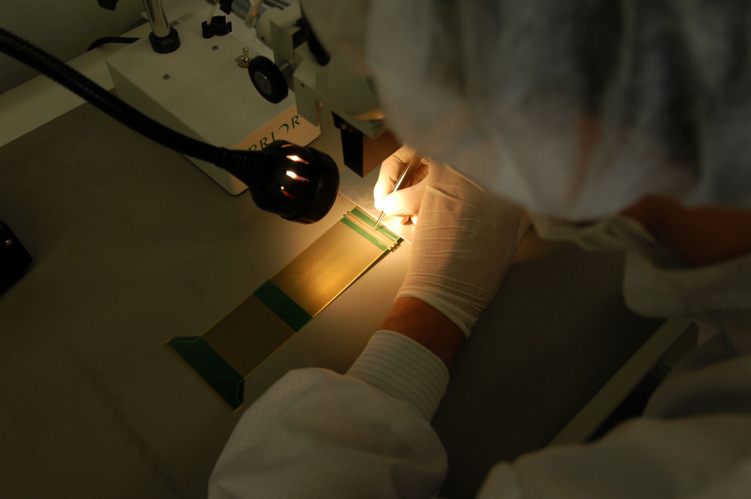
Transfering the glue to the sensor edges
|
Transfering the glue to the sensor edges
|
Transfering the glue to the sensor edges
|
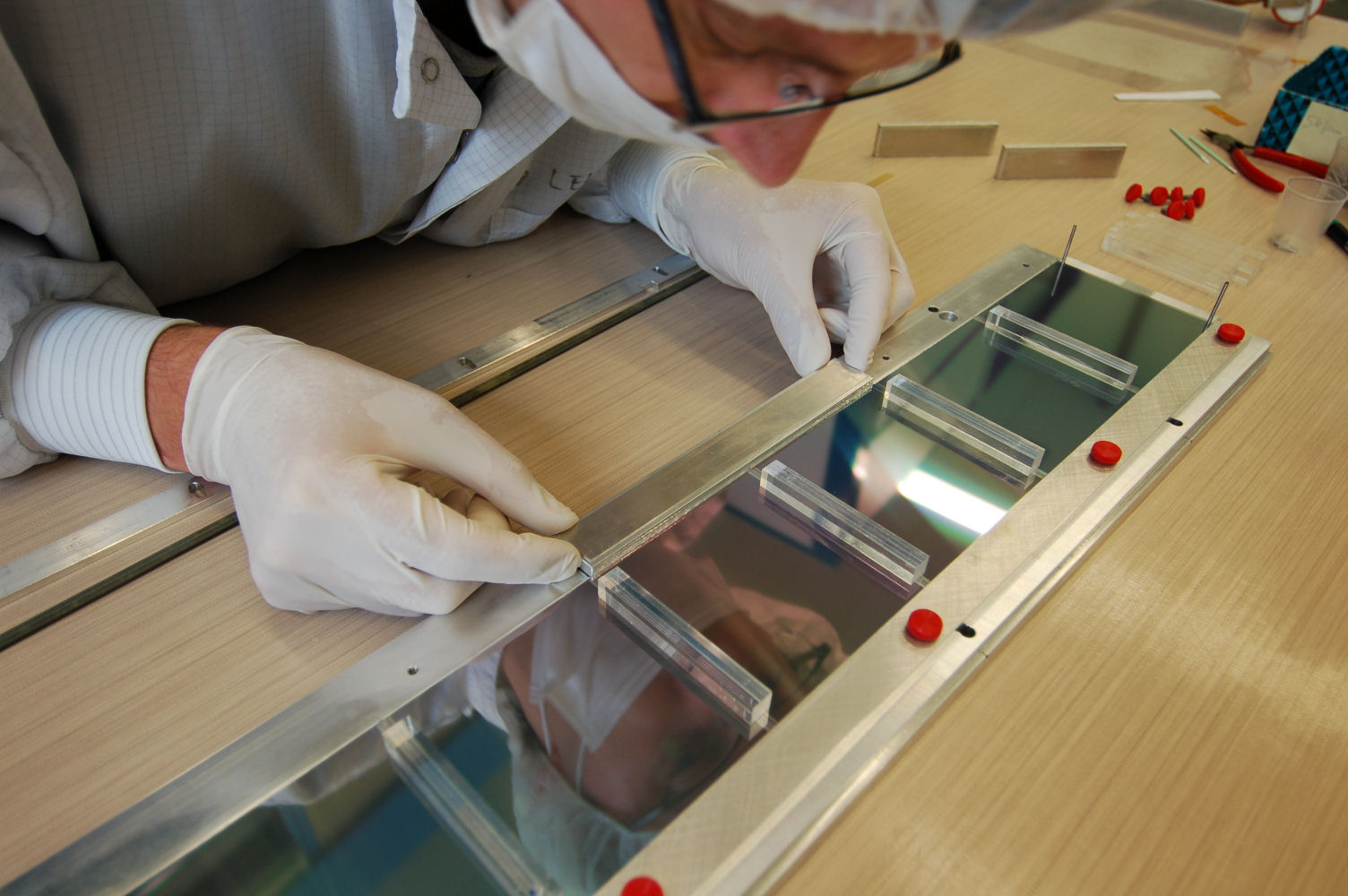
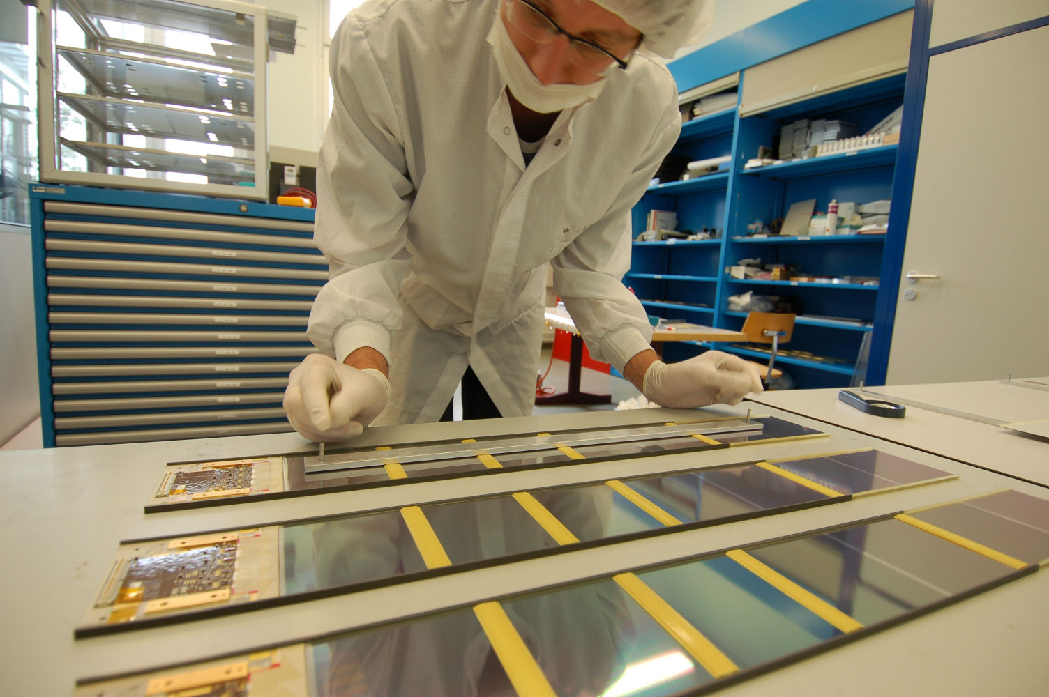
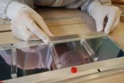
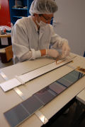
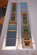
Placing the 1st rail
|
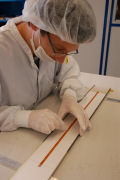
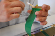
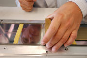
Pushing the 1st rail onto the sensor edges
|

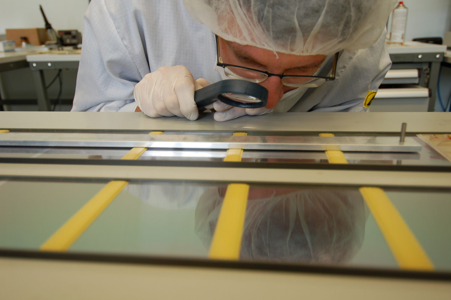
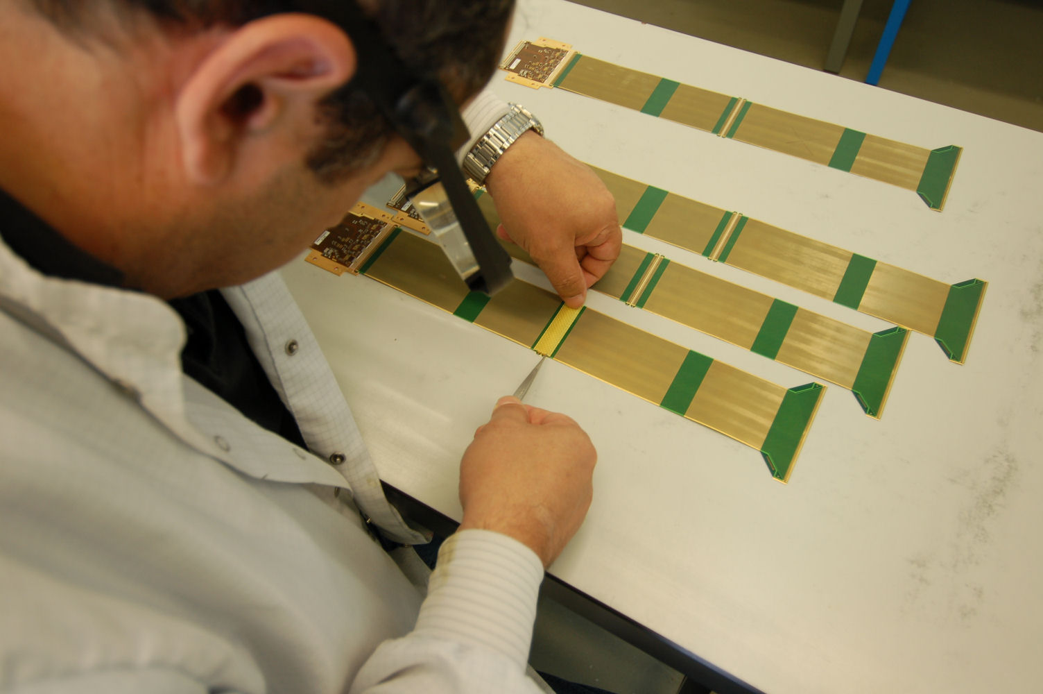
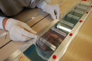
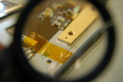
Checking the position of the 1st rail
|

Checking the position of the 1st rail
|
Placing the module under the CMM
|

Measuring the sensor alignment
|

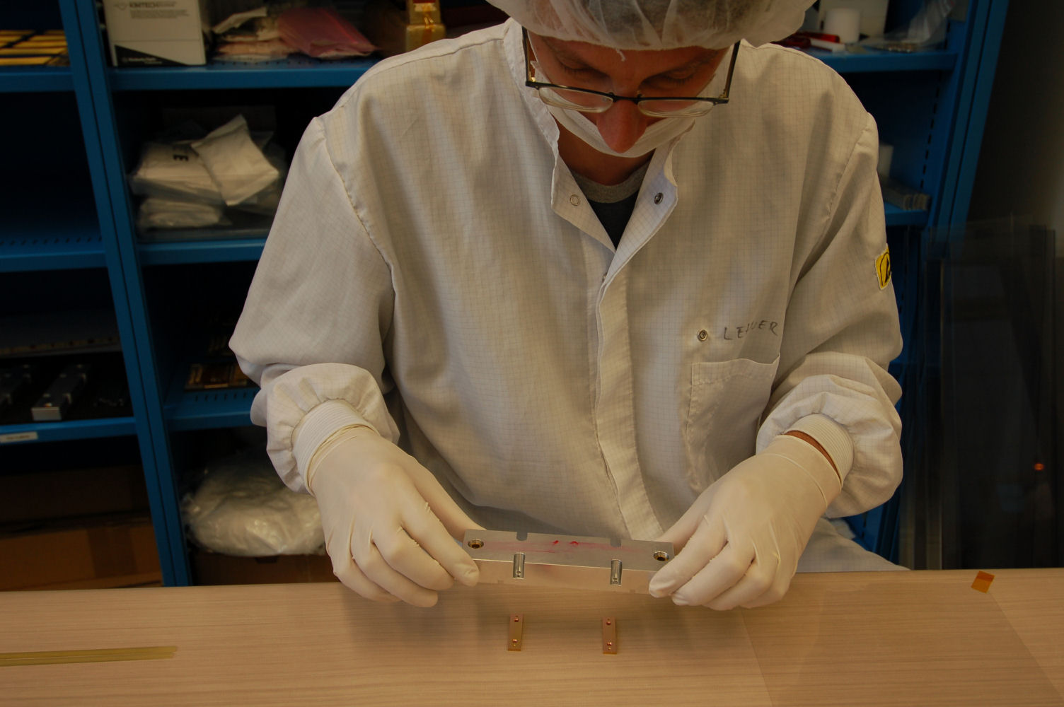
Placing the copper blocks on the mounting tool
|

Fixing the copper blocks on the mounting tool
|
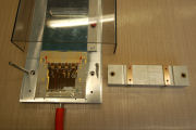
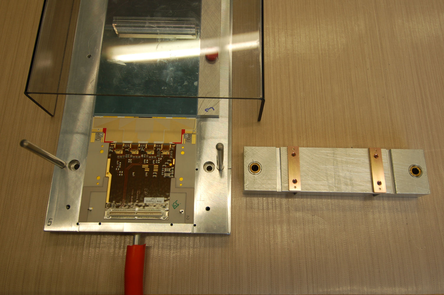
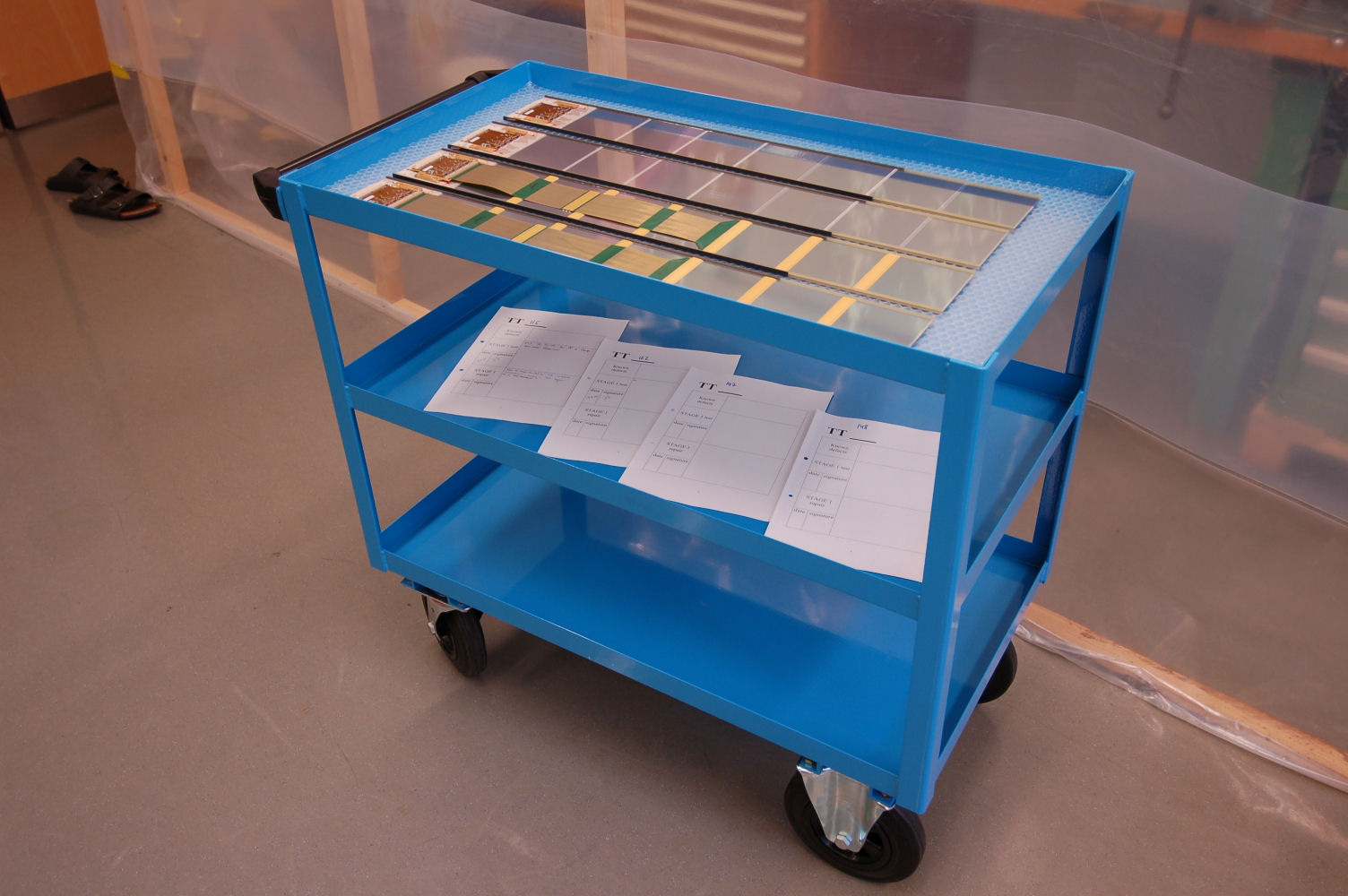
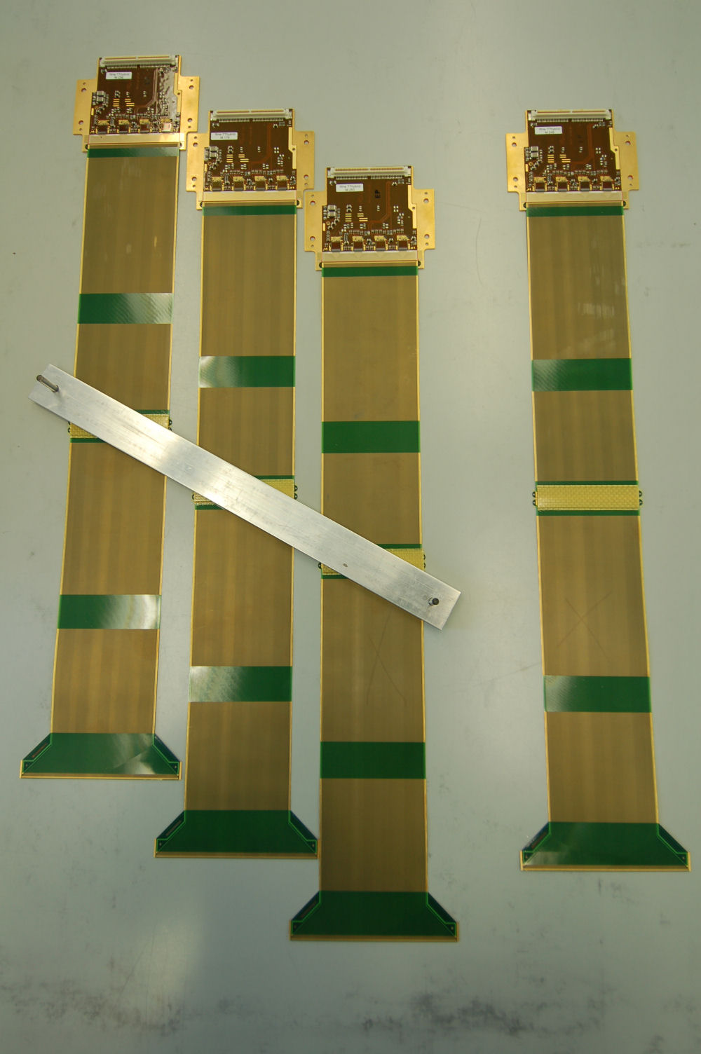
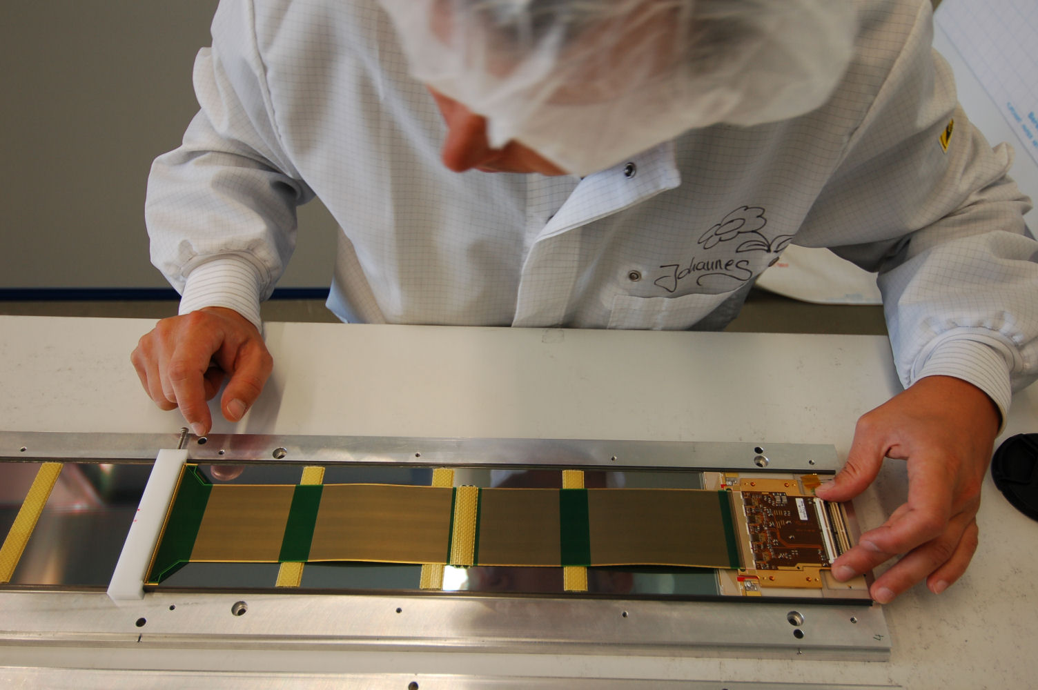
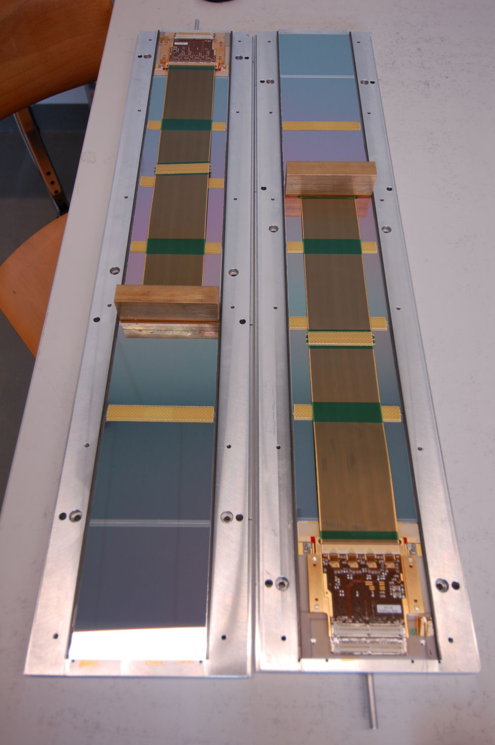
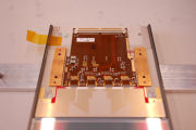
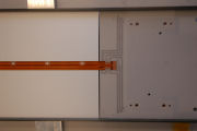
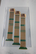
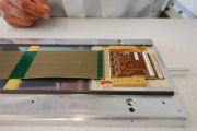
Ready for mounting onto the hybrid
|

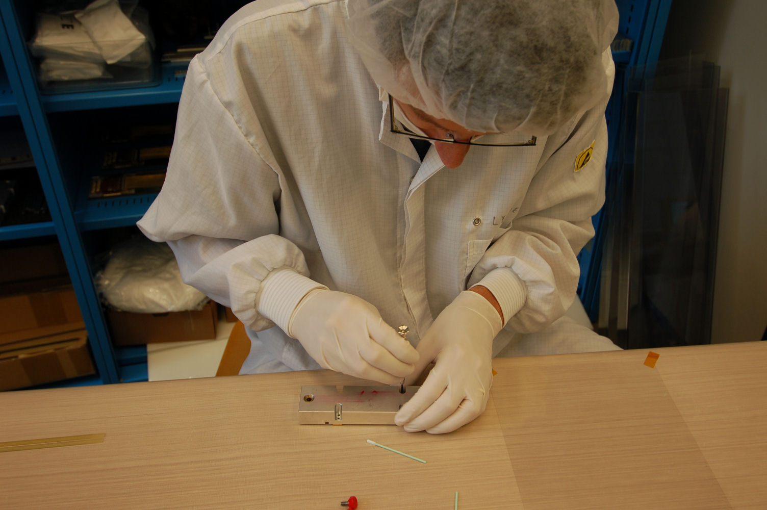
Glueing the copper blocks onto the hybrid
|
Weighting them down for the glue to cure
|
The most important task...
|
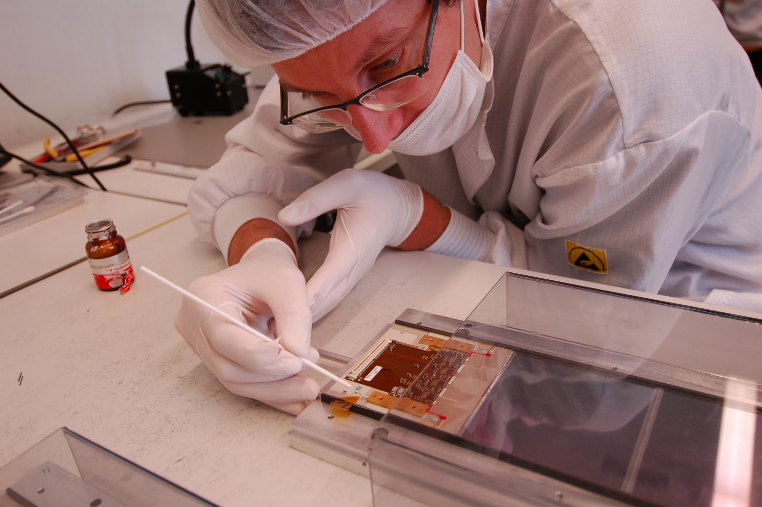
...cleaning the stencils
|
Applying a copper strap for the hybrid grounding
|

Applying a copper strap for the hybrid grounding
|
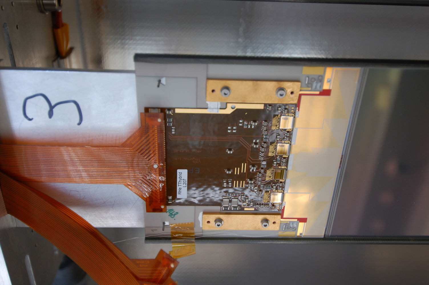
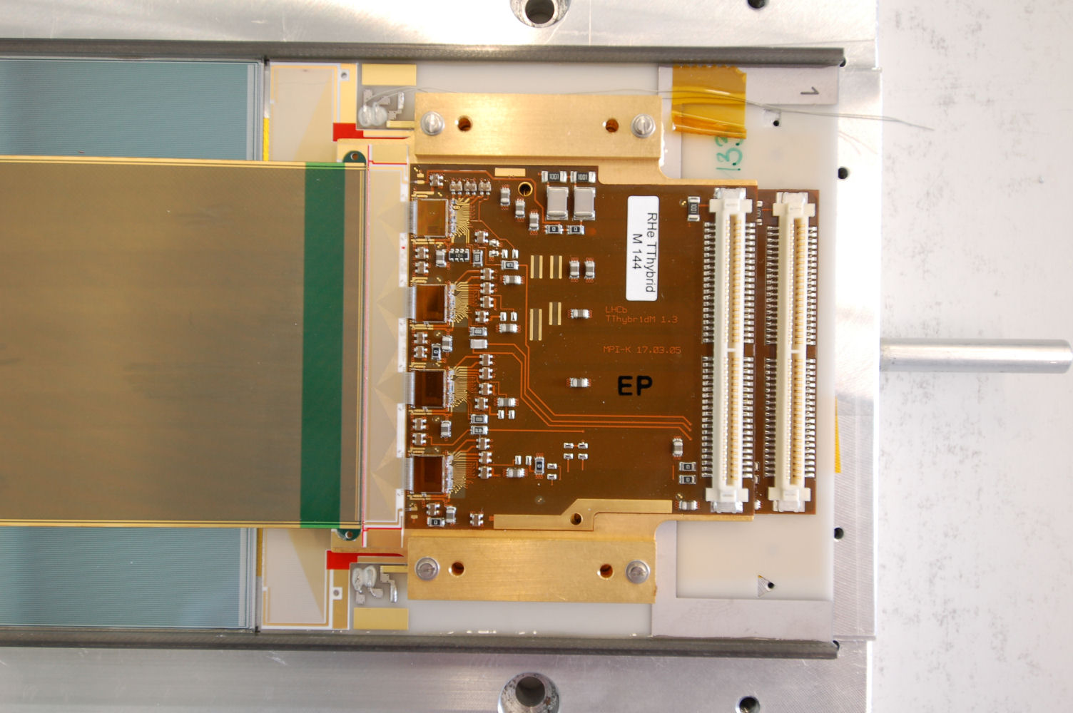
Hybrid with the copper ground strap
|
Applying silver glue for the ground connection
|

Ground connection between hybrid and copper block
|

Applying silver glue for the ground connection
|
Ground connection between hybrid and copper block
|
Mounting the bias voltage cable
|
Mounting the bias voltage cable
|
Mounting the bias voltage cable
|
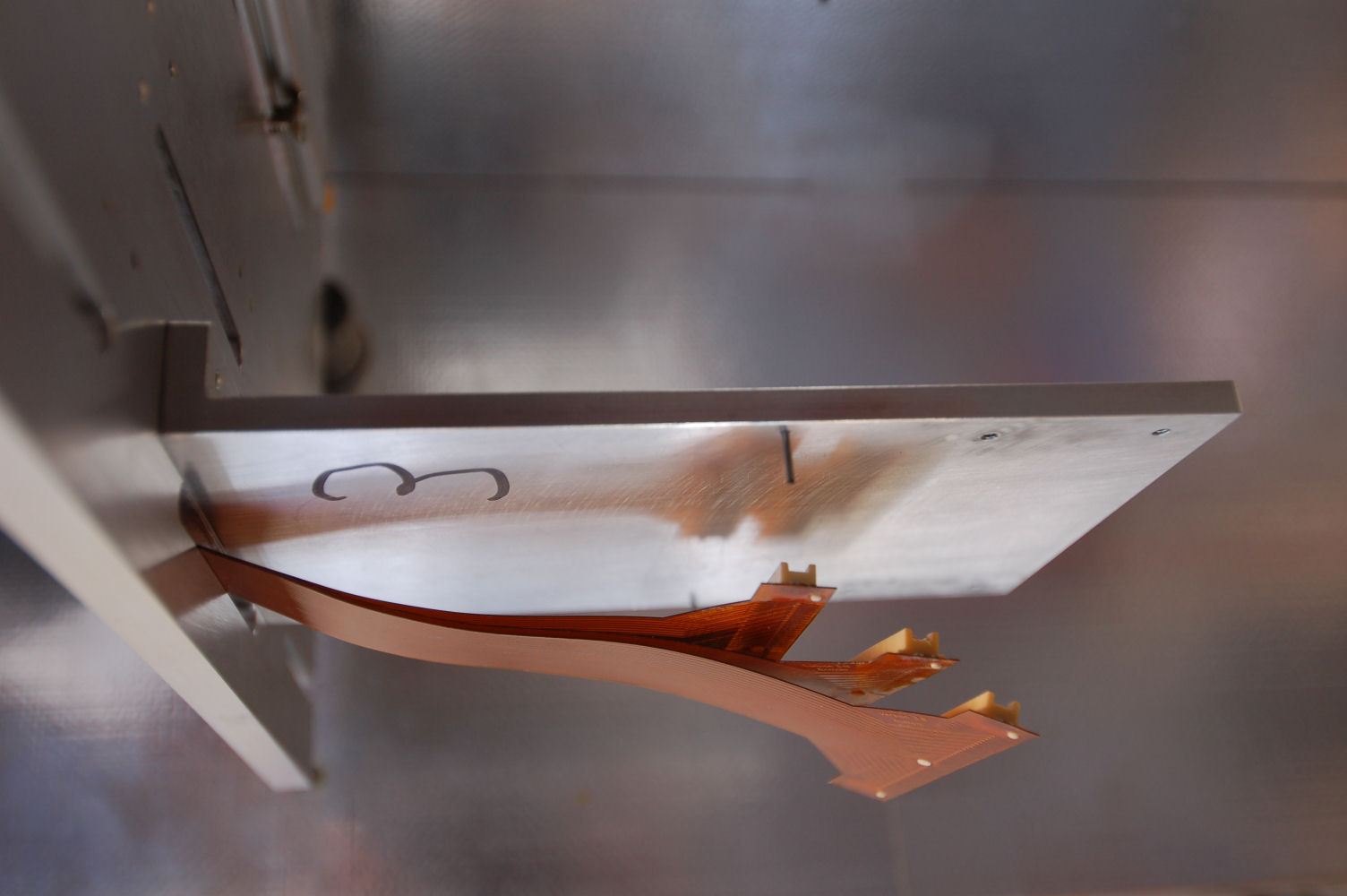
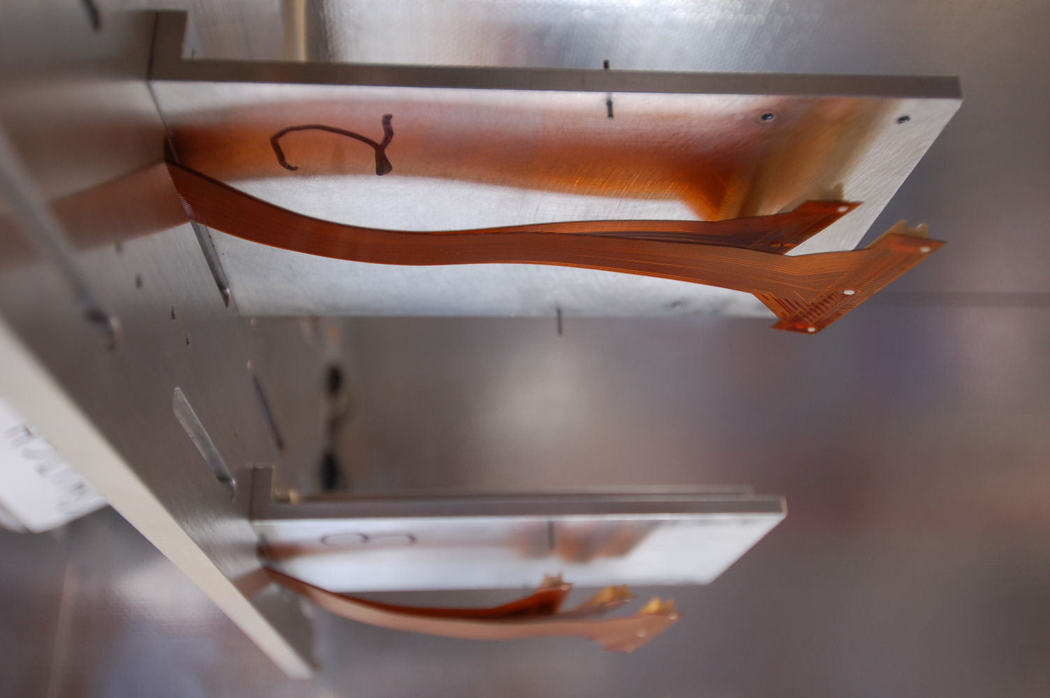
Hybrid end of the bias voltage cable
|
Applying silver glue for the connection to the sensor
|

Applying silver glue for the connection to the sensor
|
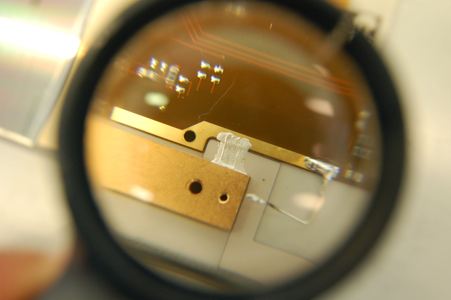
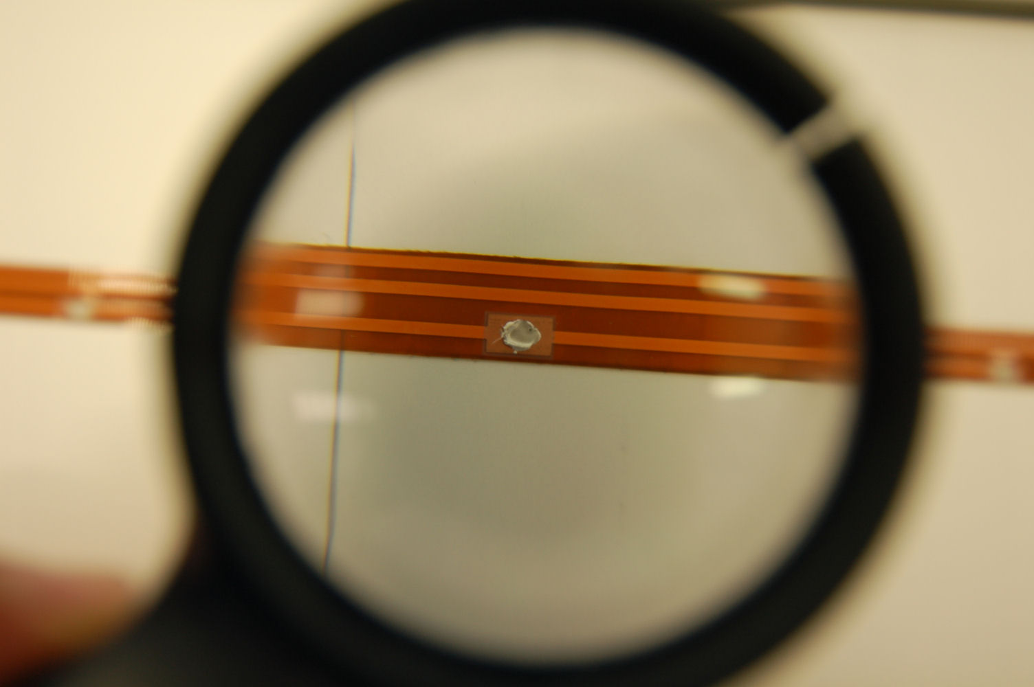
Bias voltage connection on the back of the sensor
|

Applying silver glue for the connection to the hybrid
|

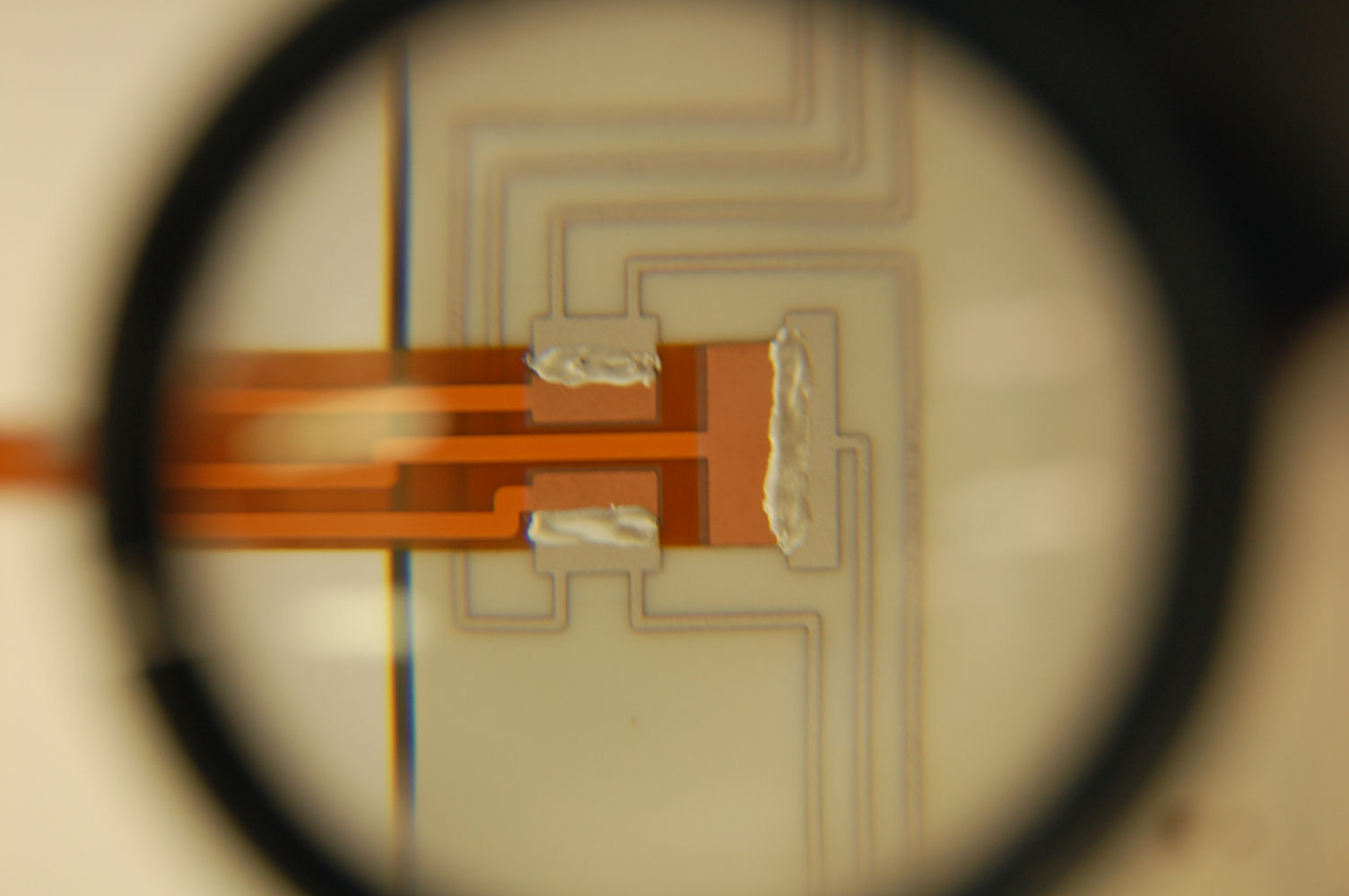
Bias voltage connection on the back of the hybrid
|
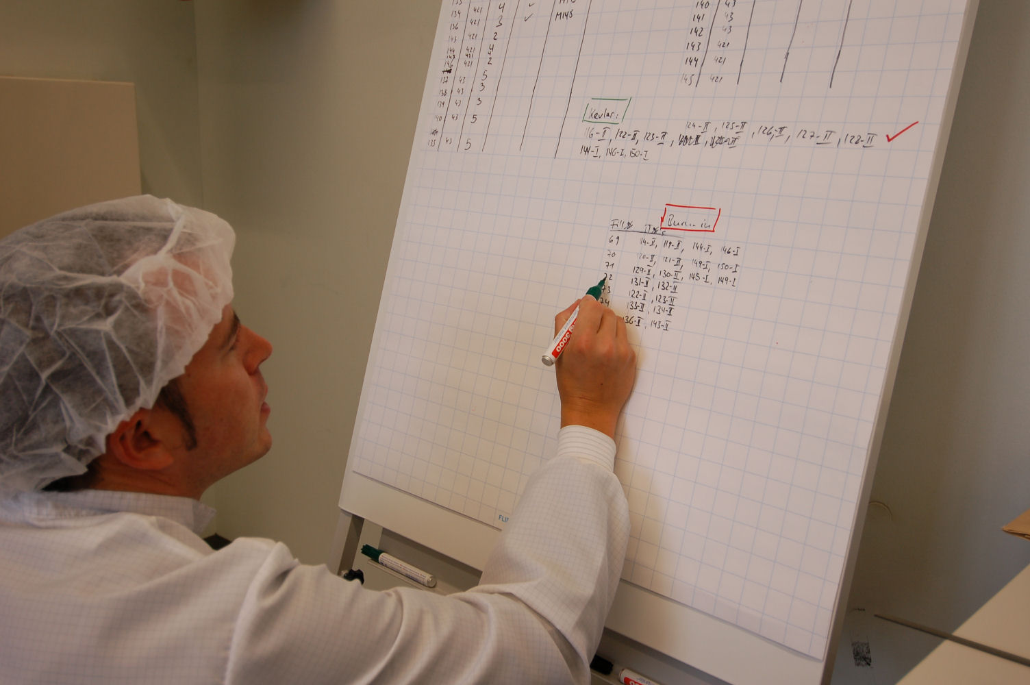
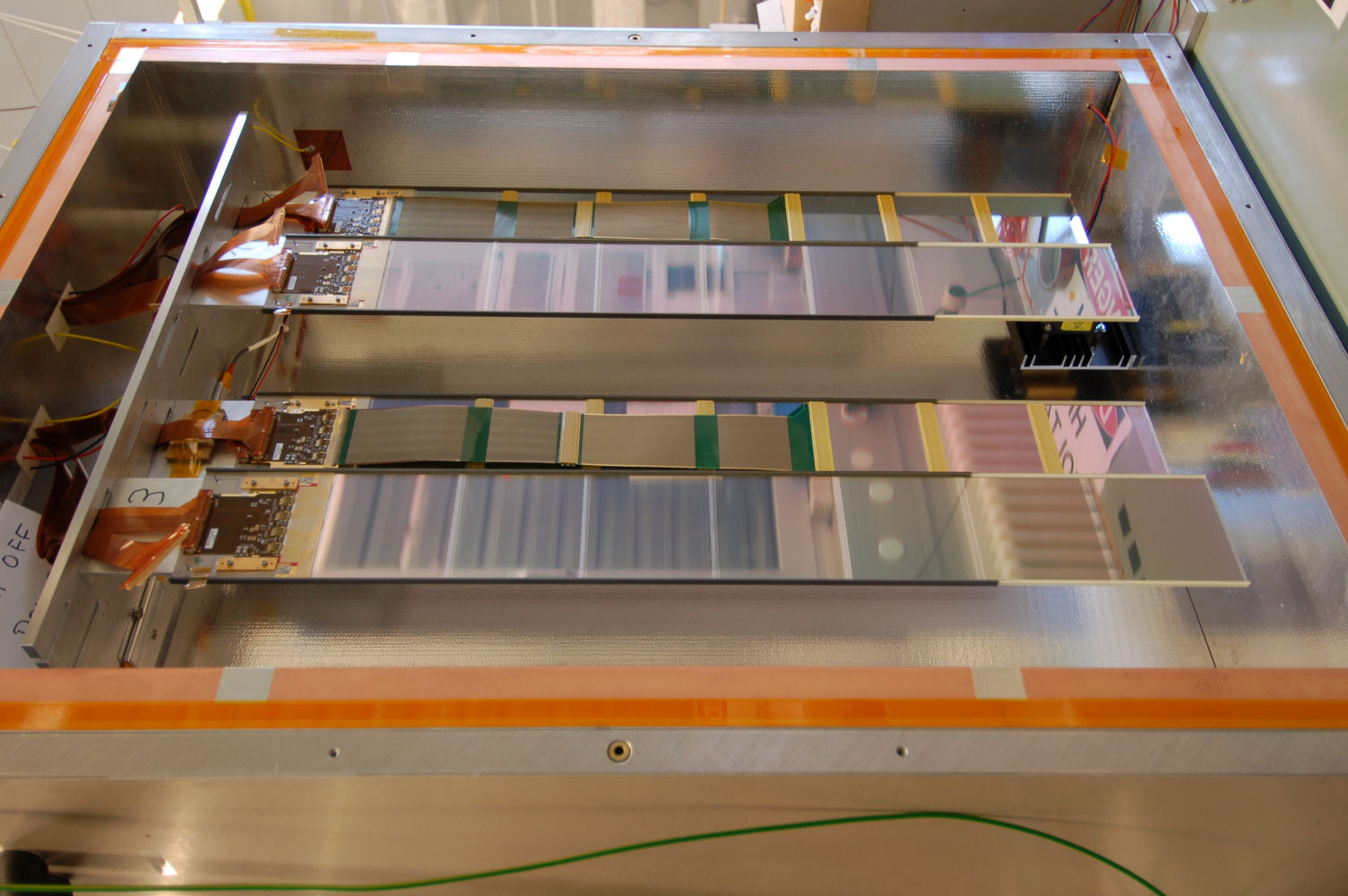
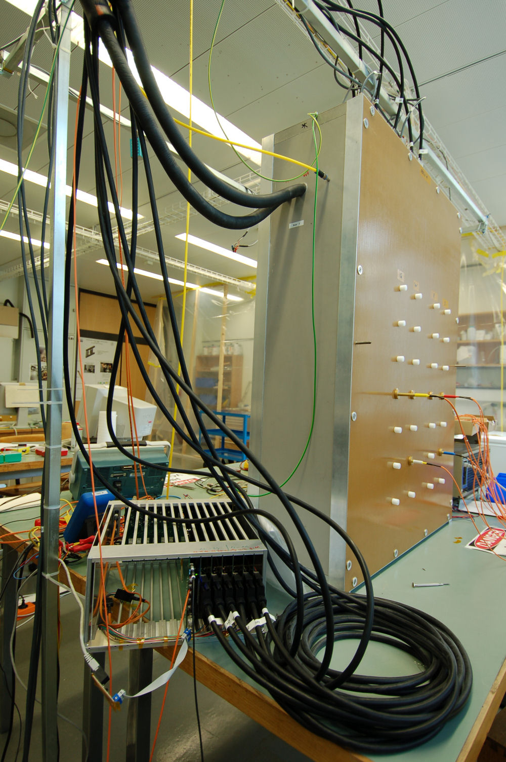
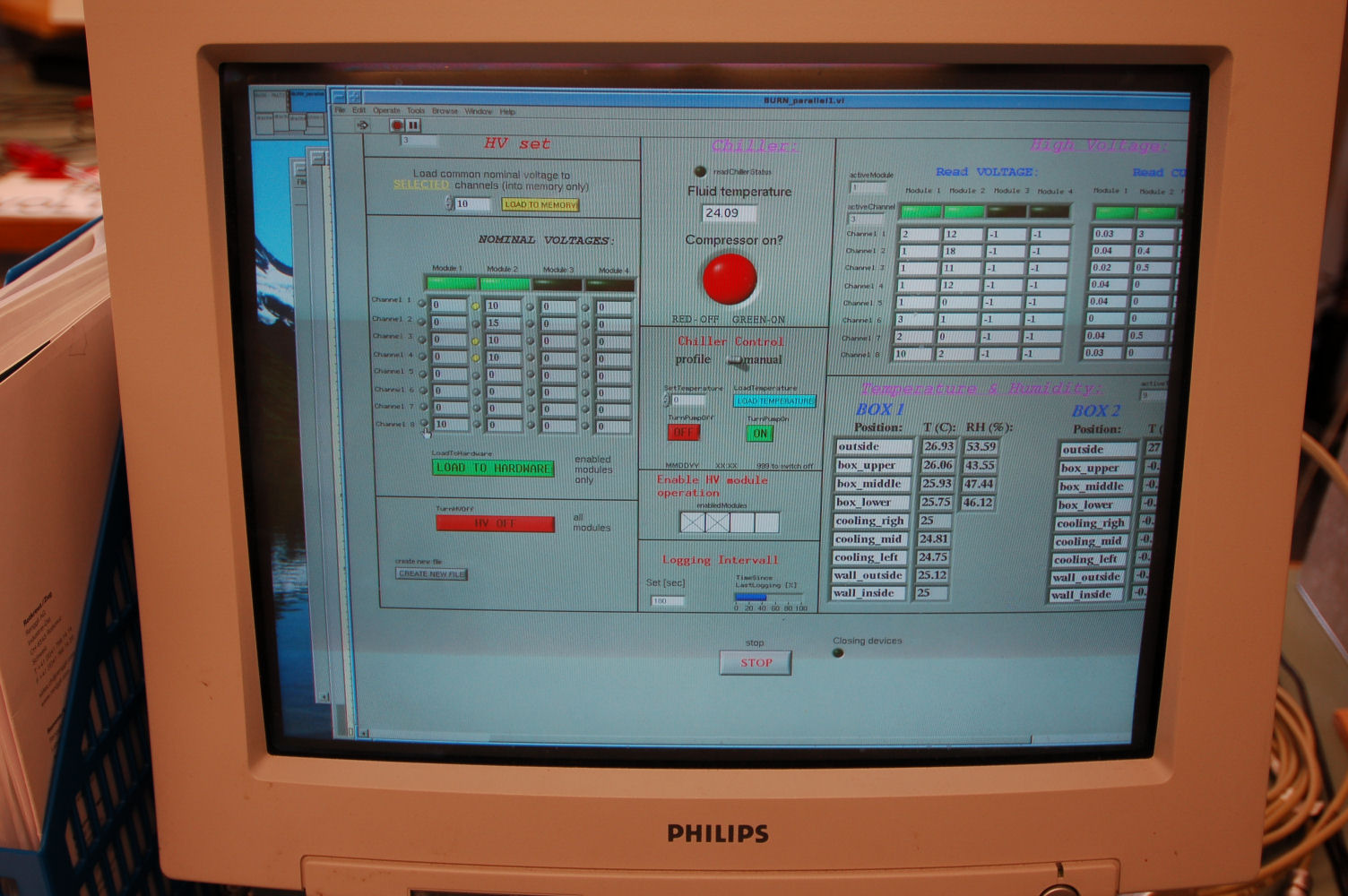
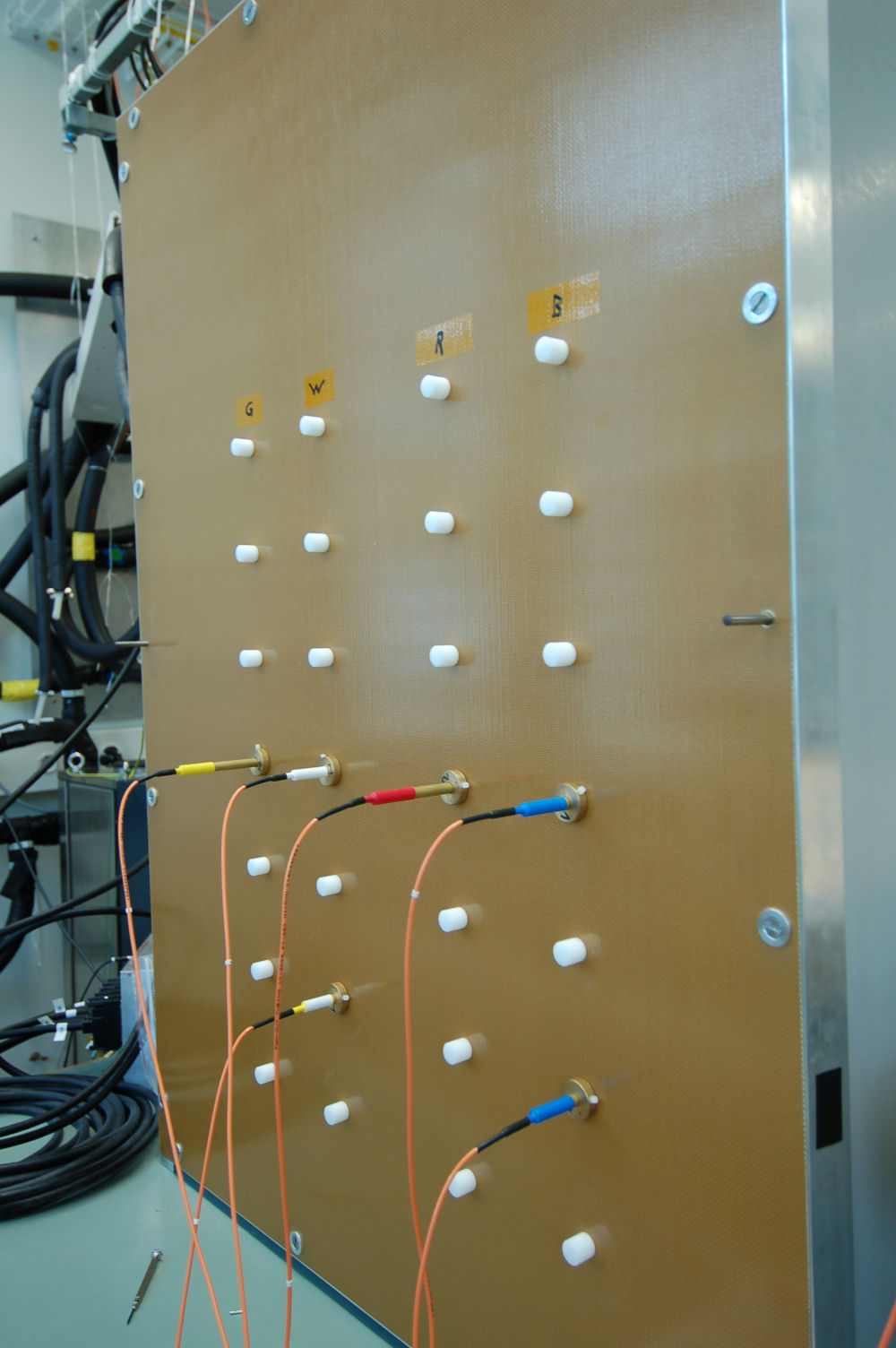
Ready for burn-in
|

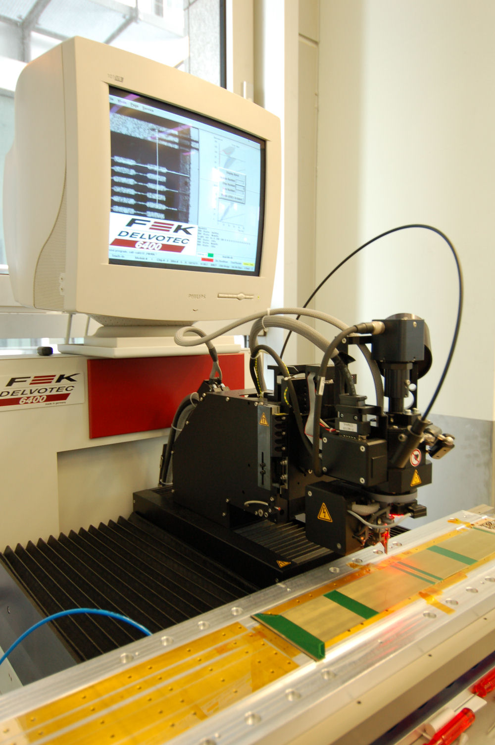
Kapton interconnect on the bond station
|

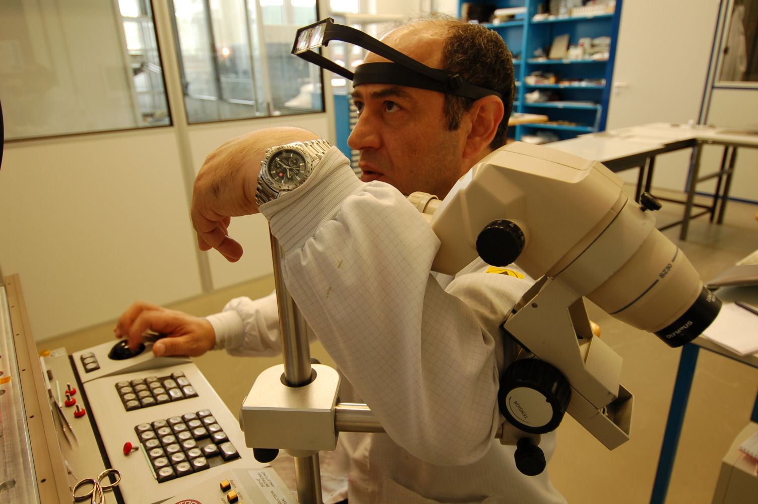
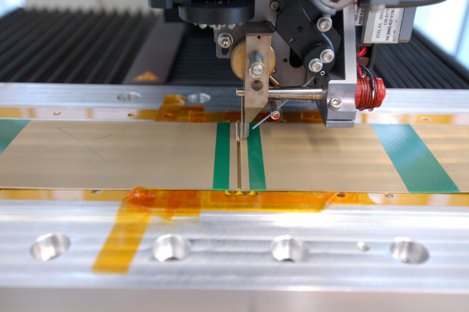
Positioning the bond head
|
Positioning the bond head
|

Bonding the two pieces of the interconnect
|
Bonds on the ground strip
|
Bonds on the signal strips
|

Pulling a broken bond
|
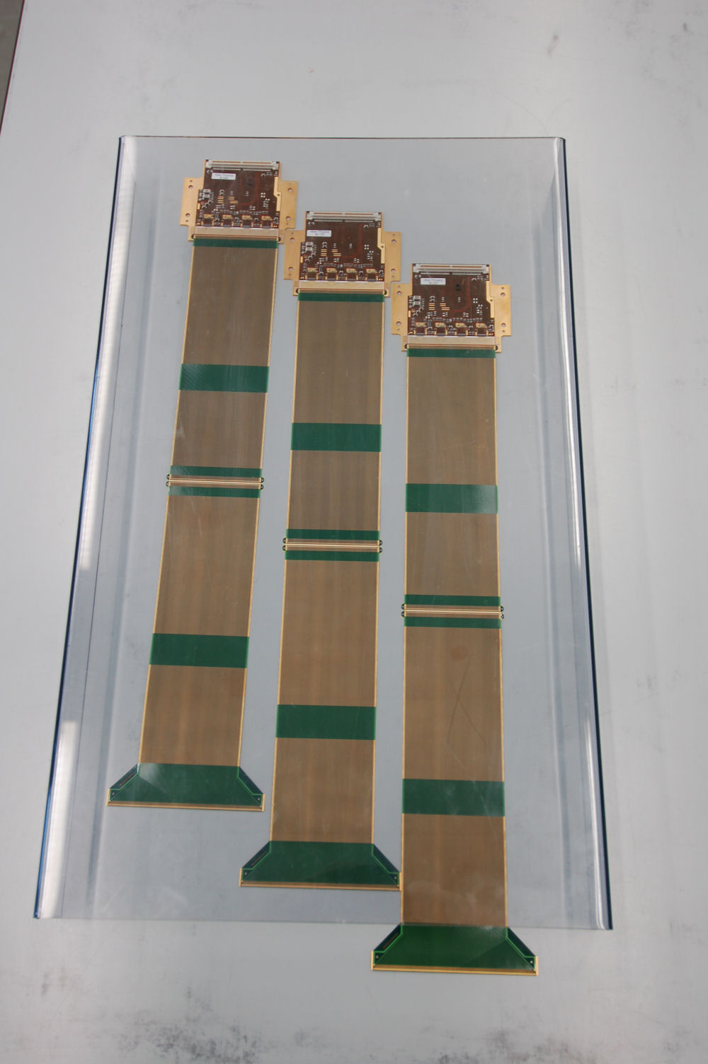
Three bonded interconnects
|
Rolling out the glue
|
Transfering the glue to the Kevlar caps
|

Glueing a Kevlar cap over the bonds
|

Weighting the Kevlar caps down for the glue to cure
|

Placing the positioning tool
|

Fixing the positioning tool
|

Checking the positioning tool
|

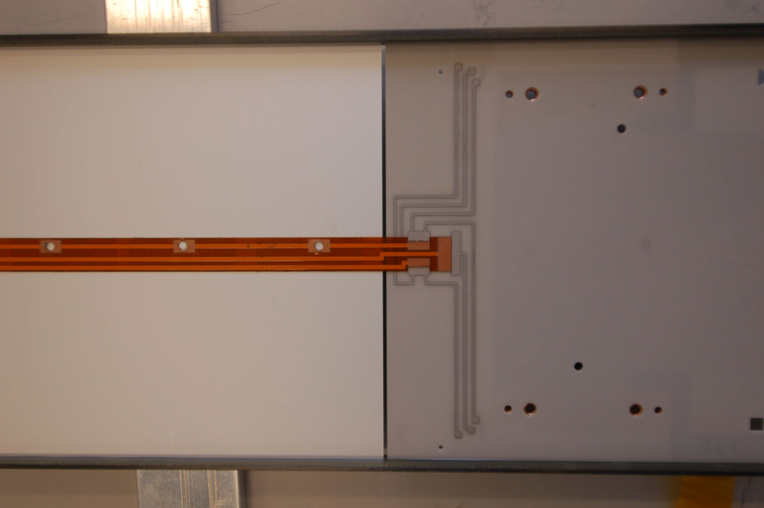
Placing the interconnect cable
|
Self-adhesive tape on the sensor end
|
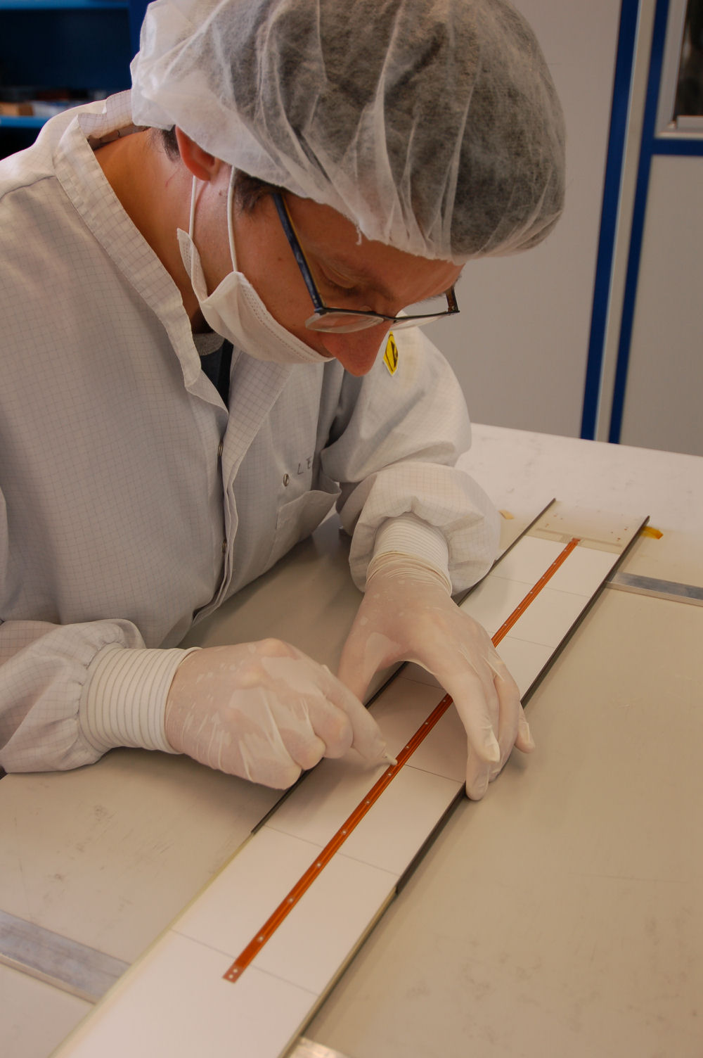
Fixing the interconnect cable on the sensor
|
Placing a weight for glue curing
|
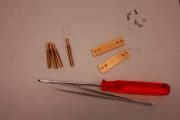
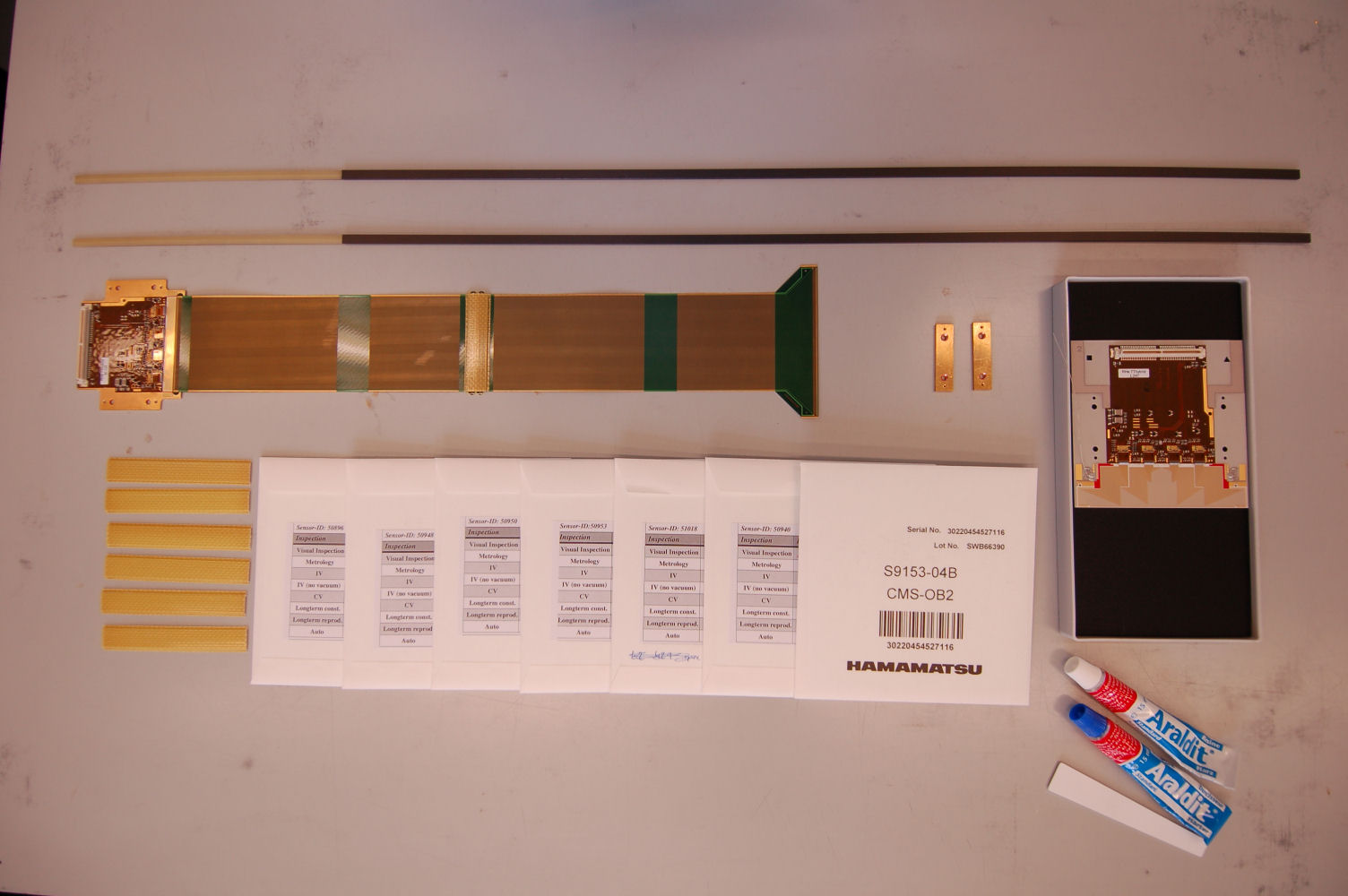
Screws, positioning pins and copper blocks
|
Placing the hybrid and copper blocks
|

Placing the washers
|
Placing the screws
|

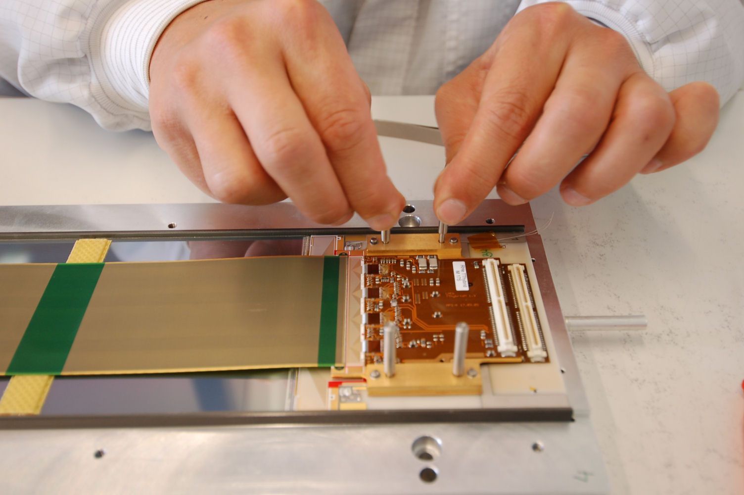
Placing the positioning pins
|

Fixing the screws
|
Done
|
Waiting for the glue to cure
|
Waiting for the glue to cure
|